
Electronic device including antenna

a technology of electronic devices and antennas, applied in the direction of antennas, antenna details, basic electric elements, etc., can solve the problems of high path loss, strong straightness of 20 ghz or more used in the 5g antenna, etc., and achieve the effect of reducing the number of cables to be mounted in the electronic device and reducing the cos

Active Publication Date: 2021-10-05
SAMSUNG ELECTRONICS CO LTD
View PDF20 Cites 0 Cited by
  • Summary
  • Abstract
  • Description
  • Claims
  • Application Information

AI Technical Summary

Benefits of technology

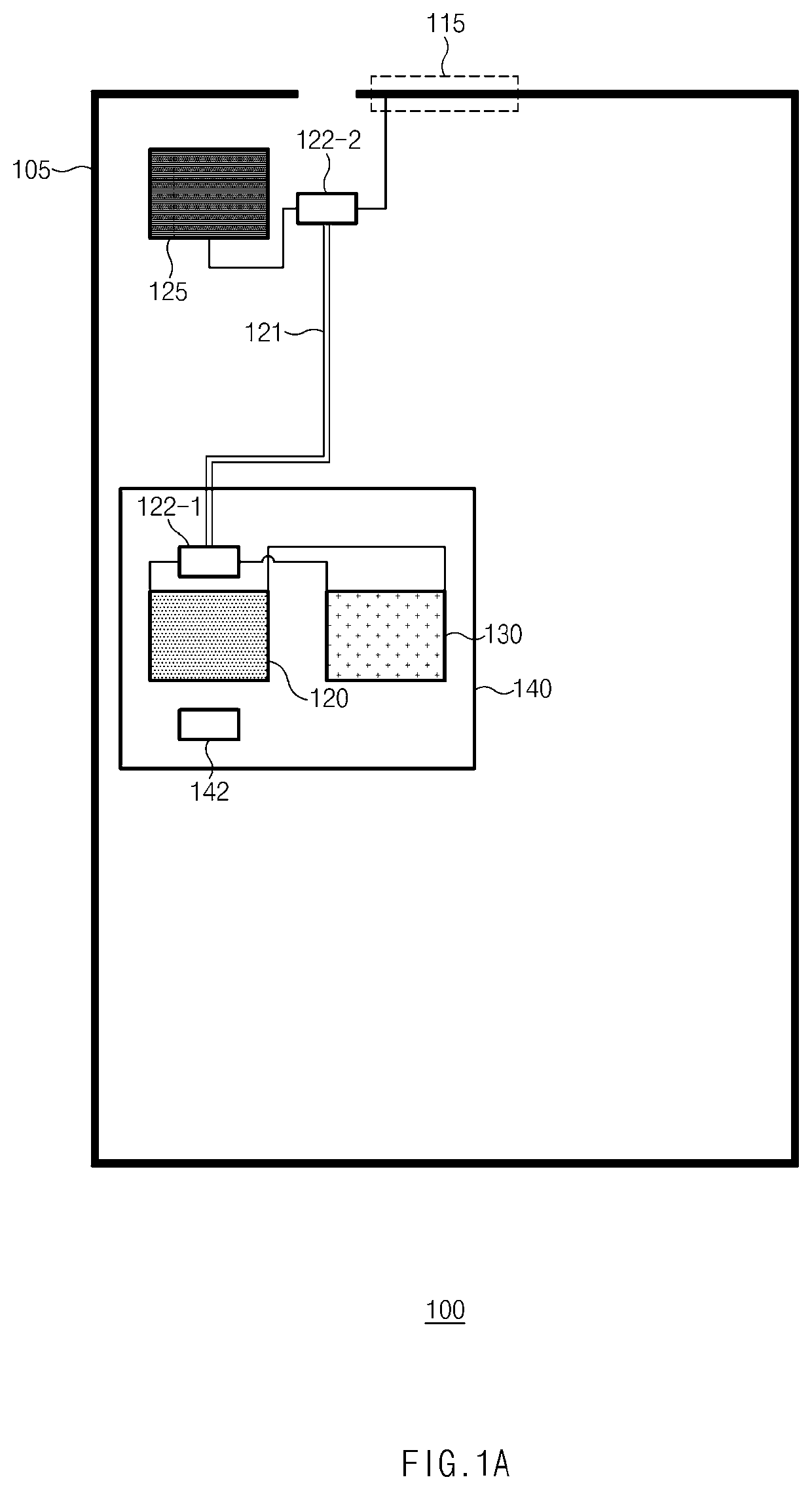
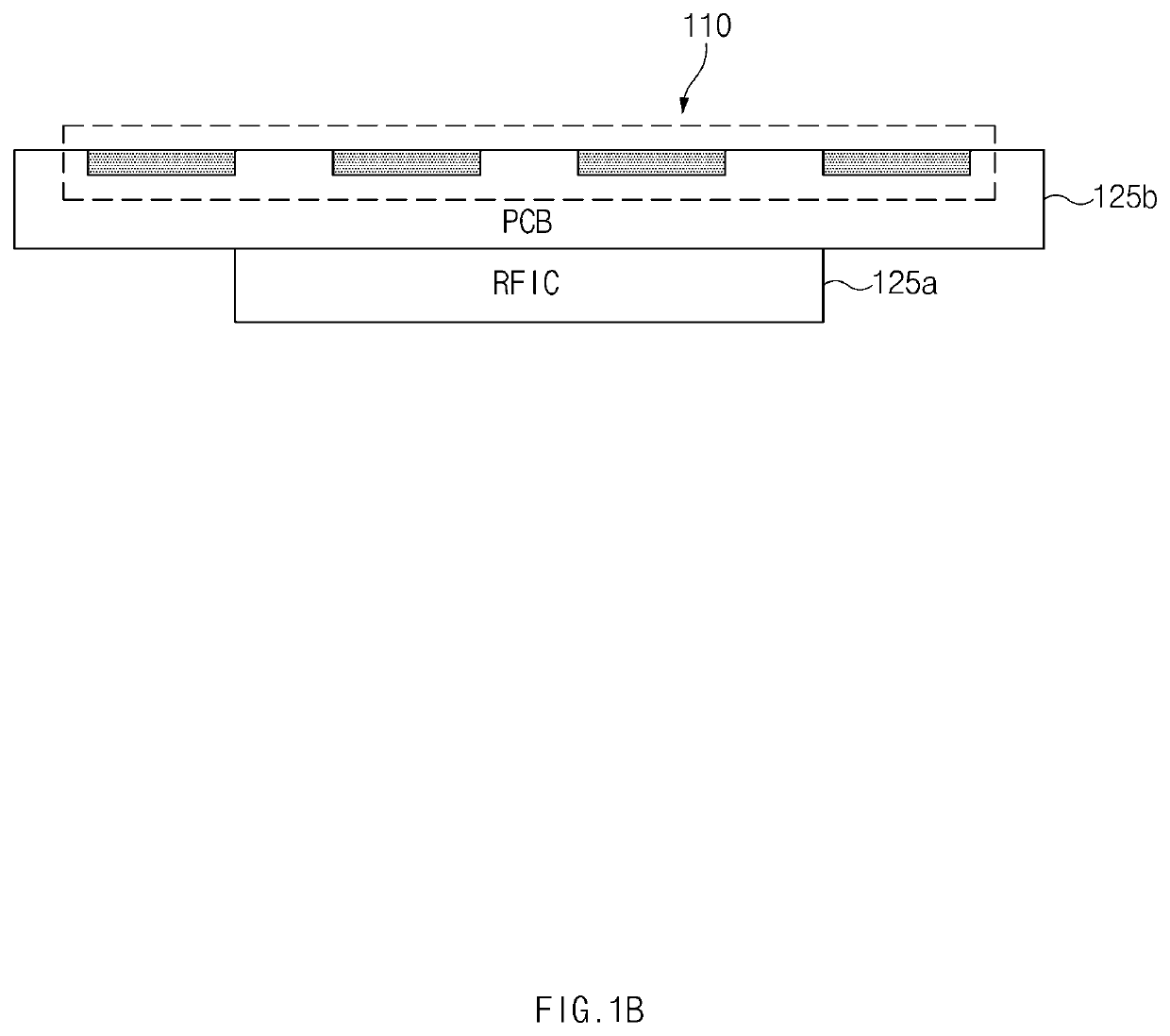
[0005]The high frequency of 20 GHz or more used in the 5G antenna has strong straightness and high path loss. For example, when the 5G antenna is mounted on the electronic device, a radio frequency integrated circuit (RFIC) for the 5G antenna may be positioned to be close to the 5G antenna. For example, a 5G antenna may be placed away from an intermediate frequency integrated circuit (IFIC) or processor. The RFIC and IFIC, and the RFIC and the processor may be electrically connected through a cable.
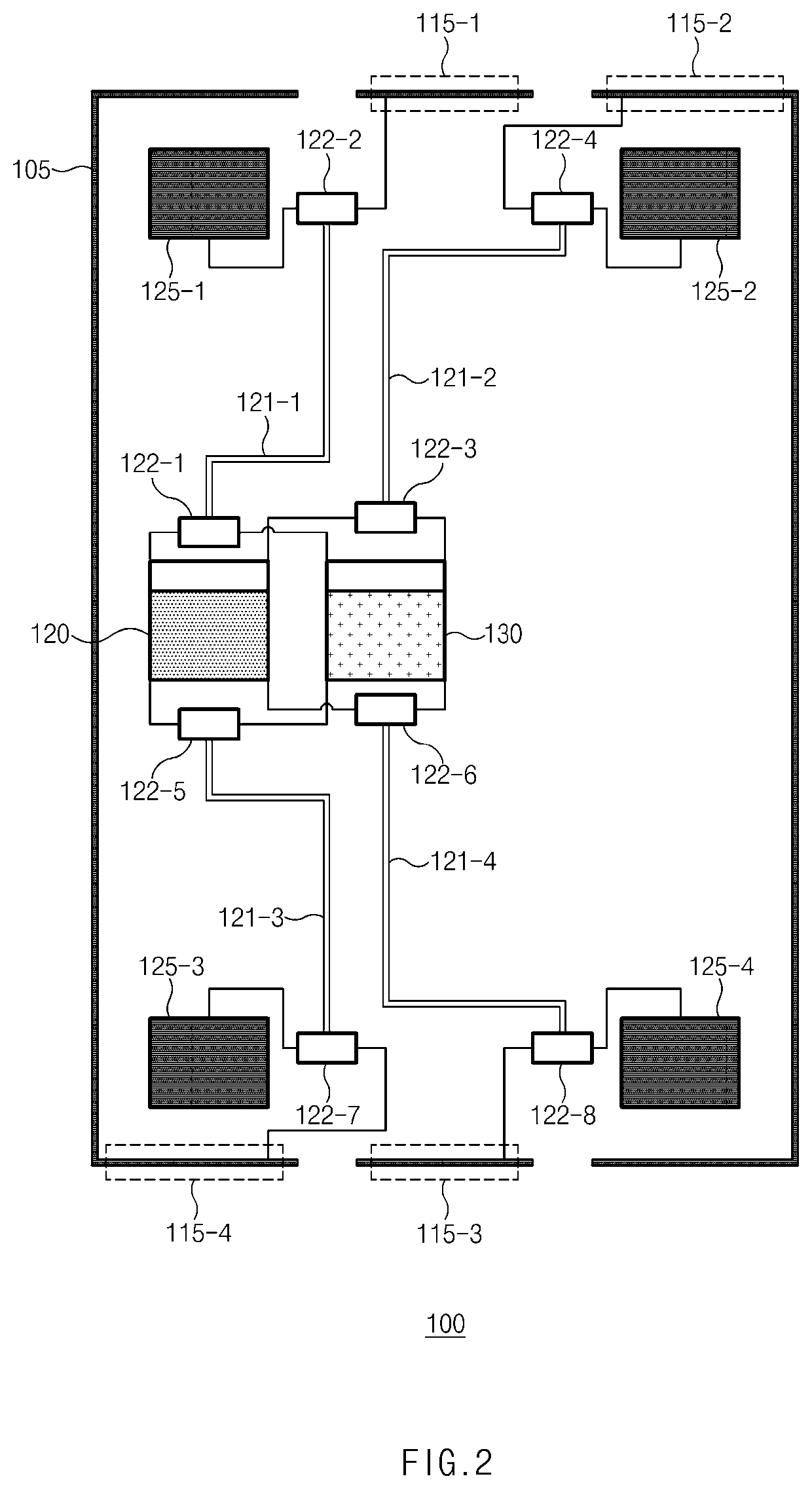
[0010]According to an embodiment disclosed in the disclosure, the number of cables to be mounted in the electronic device is reduced, thereby ensuring the inner space of the electronic device and reducing cost.

Problems solved by technology

The high frequency of 20 GHz or more used in the 5G antenna has strong straightness and high path loss.

Method used


Image

  • Electronic device including antenna
  • Electronic device including antenna
  • Electronic device including antenna

Examples


Embodiment Construction

[0020]Hereinafter, various embodiments of the disclosure may be described with reference to accompanying drawings. Accordingly, those of ordinary skill in the art will recognize that modification, equivalent, and / or alternative on the various embodiments described herein can be variously made without departing from the scope and spirit of the disclosure. With regard to description of drawings, similar components may be marked by similar reference numerals.

[0021]In the disclosure, the expressions “have”, “may have”, “include” and “comprise”, or “may include” and “may comprise” used herein indicate existence of corresponding features (e.g., components such as numeric values, functions, operations, or parts) but do not exclude presence of additional features.

[0022]In the disclosure, the expressions “A or B”, “at least one of A or / and B”, or “one or more of A or / and B”, and the like may include any and all combinations of one or more of the associated listed items. For example, the term...


PUM


Abstract

An electronic device according to an embodiment disclosed in the present document comprises: a housing; a first antenna element placed on the housing, or at a first position inside the housing; a second antenna element placed on the housing, or at a second position inside the housing; a communication processor; and at least one communication circuit electrically connected to the first antenna element and the second antenna element, wherein the at least one communication circuit can comprise: a first RF circuit, which generates an IF signal having a first frequency, a local oscillation (LO) signal of a second frequency lower than the first frequency, and a control signal of a third frequency lower than the second frequency; a second RF circuit, which provides, to the second antenna element, an RF signal of a fourth frequency higher than the third frequency and lower than the second frequency; and a third RF circuit, which receives the IF signal from the first RF circuit, up-converts the IF signal, and provides the up-converted signal to the first antenna element. In addition, various embodiments identified through the specification are possible.

Description

CROSS-REFERENCE TO RELATED APPLICATIONS[0001]This application is a 371 National Stage of International Application No. PCT / KR2018 / 013249, filed Nov. 2, 2018, which claims priority to Korean Patent Application No. 10-2017-0145365, filed Nov. 2, 2017, the disclosures of which are herein incorporated by reference in their entirety.BACKGROUND1. Field[0002]Embodiments disclosed in the disclosure relate to a 5G antenna technology included in an electronic device.2. Description of Related Art[0003]With the rapid increase in mobile traffic, a fifth generation (5G) mobile communication technology based on an ultra-high-bandwidth frequency of 20 GHz or more has been developed. The ultra-high-bandwidth frequency signal may also include millimeter waves having a frequency band of 20 GHz to 300 GHz. When an ultra-high-bandwidth frequency is used, the wavelength may be shortened, so small-size and light-weight antennas and devices are possible. In addition, a larger number of antennas may be moun...

Claims


Application Information

Patent Timeline
Patent Type & Authority Patents(United States)
IPC IPC(8): H04B1/401H01Q1/42H01Q1/38H01Q1/50
CPCH01Q1/42H01Q1/38H01Q1/50H04B1/401H01Q21/28H01Q1/243
Inventor PARK, SUNG CHULKIM, HYUNG WOOK
Owner SAMSUNG ELECTRONICS CO LTD
Learn More