
Light emitting device

Inactive Publication Date: 2010-06-10
SEOUL SEMICONDUCTOR
View PDF5 Cites 2 Cited by
  • Summary
  • Abstract
  • Description
  • Claims
  • Application Information

AI Technical Summary

Benefits of technology

[0049]According to the present invention so constructed, a laser diode having strong straightness is used as a light source and a light emitting material uses light having a first wavelength emitted from the laser diode to emit light having a second wavelength, so that a color-mixed light can be implemented.
[0050]Since the laser diode is used as a light source, the color-mixed light implemented by the light emitting device of the present invention has strong straightness, so that it can be effectively used for long-distance illumination and flash.

Problems solved by technology

However, since the light emitting diode has a wide emission angle of a light source and poor straightness, the light emitting diode has currently been used only for short-distance illumination and has a limitation in being used for long-distance illumination and flasher.

Method used


Image

  • Light emitting device
  • Light emitting device
  • Light emitting device

Examples


Embodiment Construction

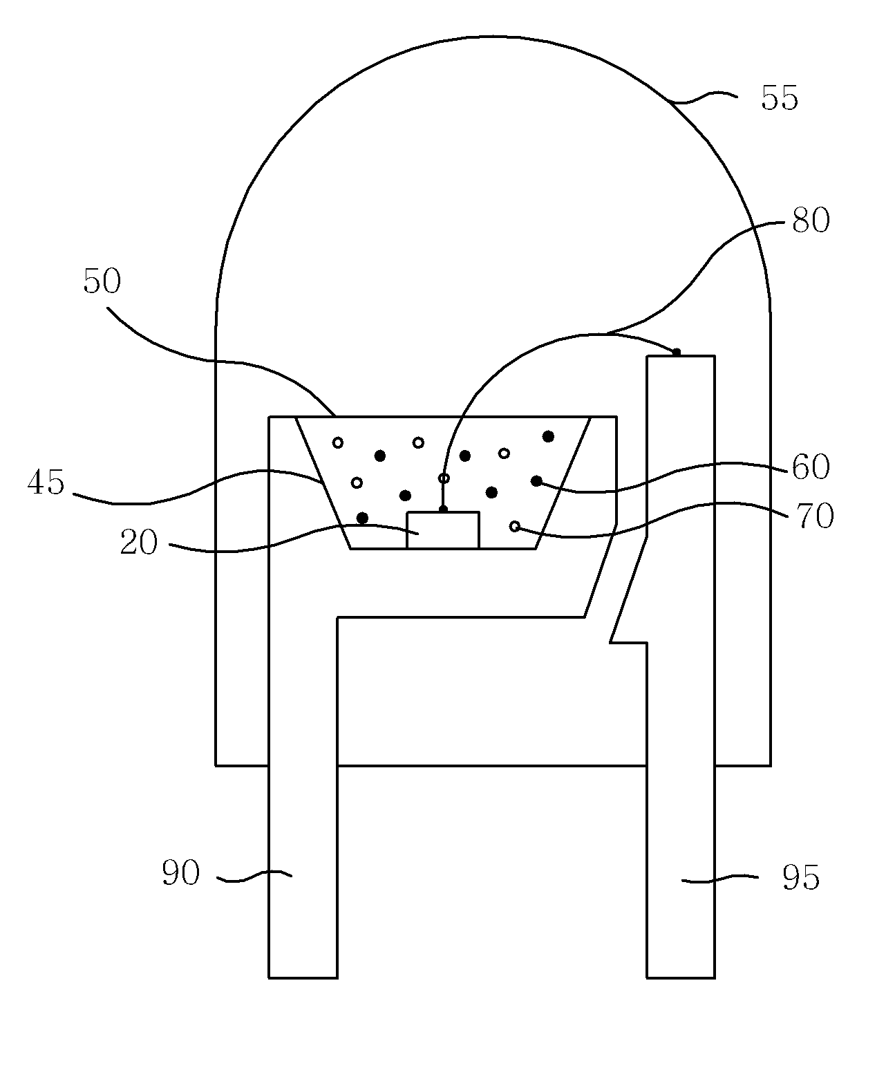
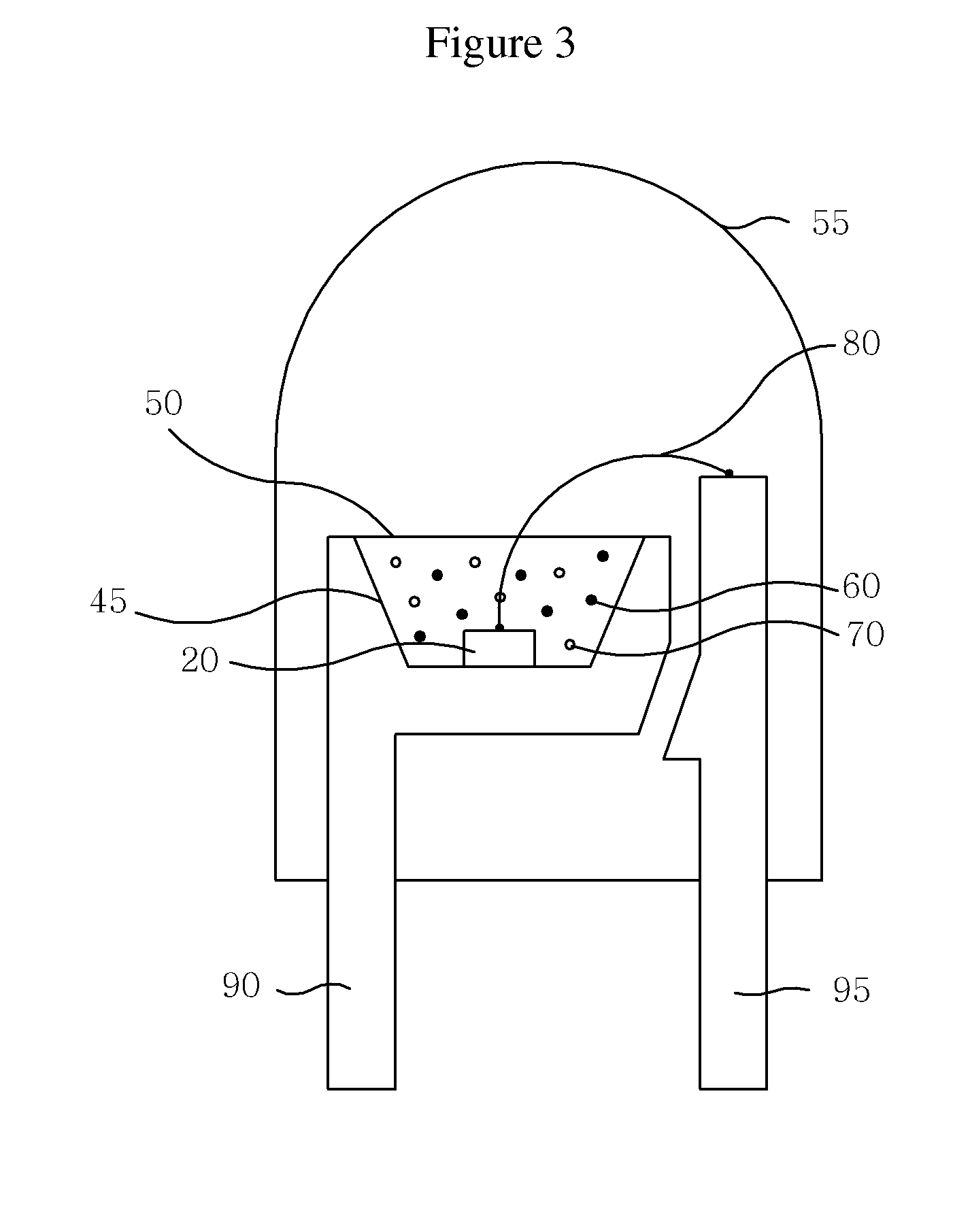
[0056]Hereinafter, a light emitting device according to the present invention will be described in detail with reference to the accompanying drawings. However, the present invention is not limited to the embodiments set forth herein but can be implemented in various forms different from each other. Rather, the embodiments are merely provided to allow the present invention to be completely described herein and to fully convey the scope of the invention to those skilled in the art.

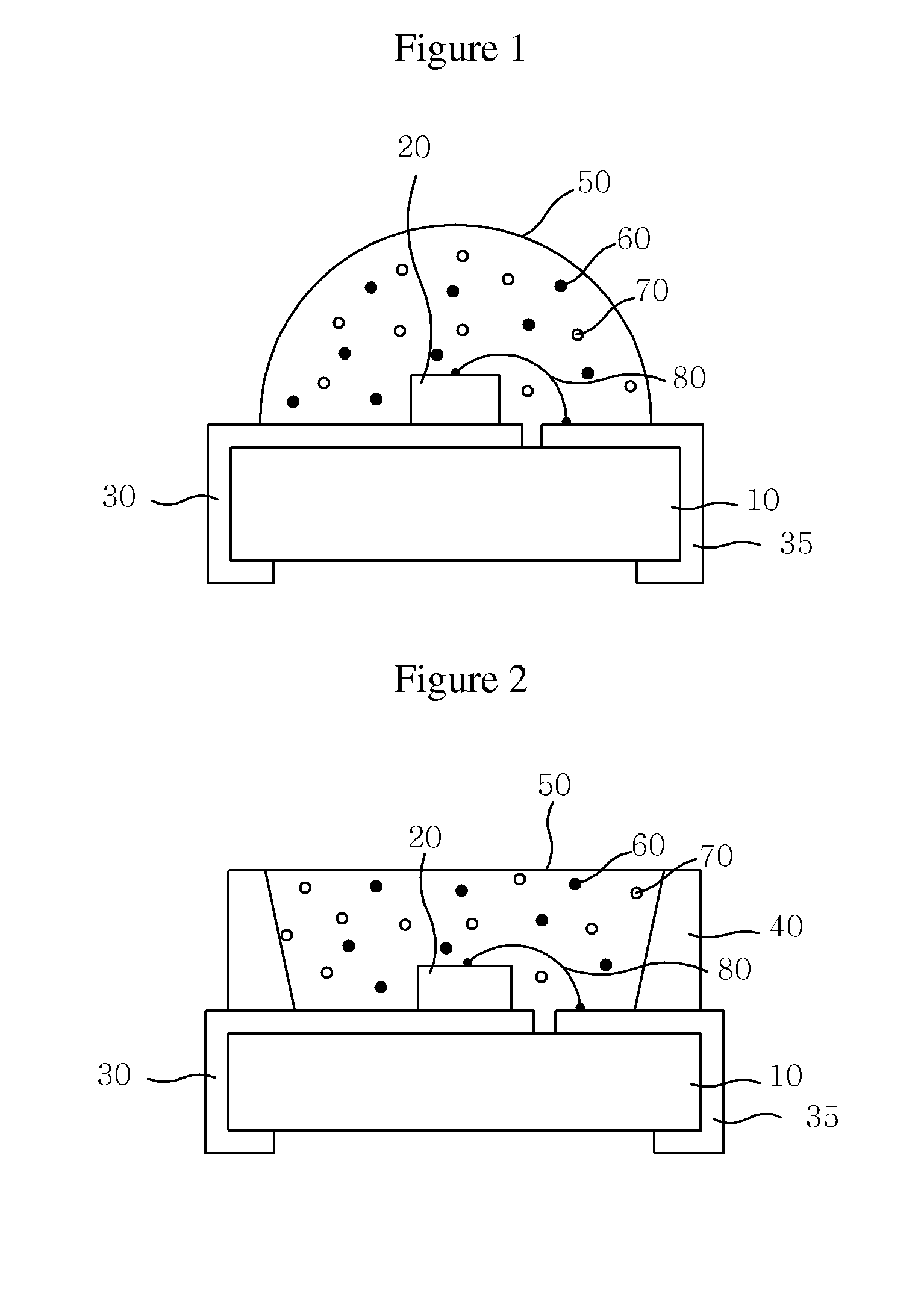
[0057]FIG. 1 is a sectional view showing a chip type light emitting device according to an embodiment of the present invention.

[0058]Referring to FIG. 1, the light emitting device comprises a substrate 10, first and second electrodes 30 and 35 formed on the substrate 10, a laser diode 20 mounted on the first electrode 30, and a molding portion 50 for encapsulating the laser diode 20. Light emitting materials 60 and 70 are uniformly mixed and distributed in the molding portion 50.

[0059]The substrate 10 may be...


PUM


Abstract

According to the present invention, there is provided a light emitting device, which comprises at least one laser diode configured to emit light in at least one first wavelength region selected from spectrum regions including ultraviolet ray, blue light and green light; and a light emitting material for emitting light in a second wavelength region by the light in the first wavelength region emitted from the laser diode, the second wavelength region being different from the first wavelength region, wherein a color-mixed light is made by the light in the first wavelength region and the light in the second wavelength region. Since the laser diode having strong straightness is used as a light emission source, the color-mixed light implemented by the light emitting device of the present invention has strong straightness, so that it may be effectively used for long-distance illumination and flash.

Description

CROSS-REFERENCE TO RELATED APPLICATIONS[0001]This application is the National Stage of International Application No. PCT / KR2008 / 002512, filed May 2, 2008, and claims priority from and the benefit of Korean Patent Application No. 10-2007-0043799, filed on May 4, 2007, which are both hereby incorporated by reference for all purposes as if fully set forth herein.FIELD OF THE INVENTION[0002]The present invention relates to a light emitting device, and more specifically, to a light emitting device capable of emitting light having strong straightness, in which a laser diode having strong straightness is used as a light source and a light emitting material uses light having a first wavelength emitted from the laser diode to emit light having a second wavelength, thereby implementing a color-mixed light.DISCUSSION OF THE BACKGROUND[0003]A light emitting diode (LED) that is a representative light emitting device is a device for emitting a predetermined light through recombination of minority...

Claims


Application Information

Patent Timeline
IPC IPC(8): H01J1/62H01J1/02
CPCC09K11/0883C09K11/7731C09K11/7734H01L2933/0091C09K11/7792F21K9/00C09K11/7774C09K11/77347C09K11/77344C09K11/77348
Inventor LEE, CHUNG HOON
Owner SEOUL SEMICONDUCTOR
Learn More