Electronic device for performing beamforming in wireless communication system and method therefor

a wireless communication system and electronic device technology, applied in the field of beamforming technology of wireless communication system, can solve the problems of inefficient beam training process, difficulty in precisely adjusting beam width and beam direction, etc., and achieve the effect of efficient beamforming and efficient connection

Active Publication Date: 2021-08-10
SAMSUNG ELECTRONICS CO LTD
View PDF22 Cites 0 Cited by
  • Summary
  • Abstract
  • Description
  • Claims
  • Application Information

AI Technical Summary

Benefits of technology

[0006]Because signals in the mmWave band (e.g., 60 GHz) have stronger straightness compared to those in 2.4 GHz and 5 GHz, and path loss is very large due to frequency characteristics, a 60 GHz system using the mmWave band may mount a large number of antennas to apply beamforming technique to resolve the problem.
[0011]According to various embodiments disclosed herein, the electronic device may perform efficient beamforming by reflecting a specific event or a current state.
[0012]According to various embodiments disclosed herein, the electronic device may efficiently perform a connection between devices by reflecting a user's intention.

Problems solved by technology

In WLAN systems using the 2.4 GHz and 5 GHz bands, an antenna mounting space is insufficient due to the mounting of antennas in the unit of centimeter, thus making it difficult to precisely adjust a beam width and a beam direction even when beamforming is applied.
To form a beam pattern for connection with a target device, a beam training process needs to be performed but it may be inefficient to go through all of the beam training processes because a required beam pattern may be simple for a specific event or situation.

Method used


Image

  • Electronic device for performing beamforming in wireless communication system and method therefor
  • Electronic device for performing beamforming in wireless communication system and method therefor
  • Electronic device for performing beamforming in wireless communication system and method therefor

Examples


Embodiment Construction

[0031]Hereinafter, various embodiments of the disclosure may be described with reference to accompanying drawings. Accordingly, those of ordinary skill in the art will recognize that modification, equivalent, and / or alternative on the various embodiments described herein can be variously made without departing from the scope and spirit of the disclosure.

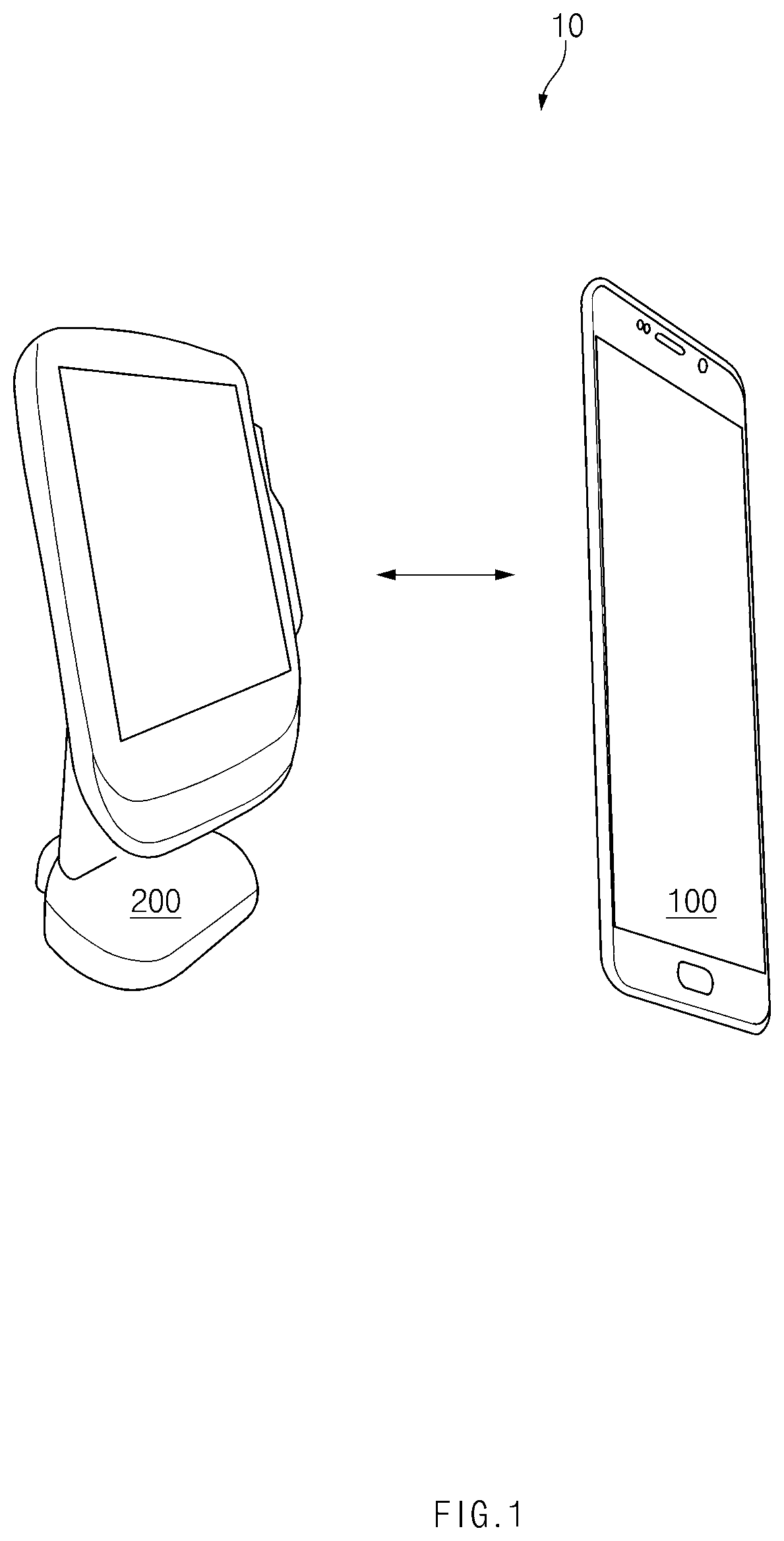
[0032]FIG. 1 illustrates a network environment of an electronic device according to an embodiment.

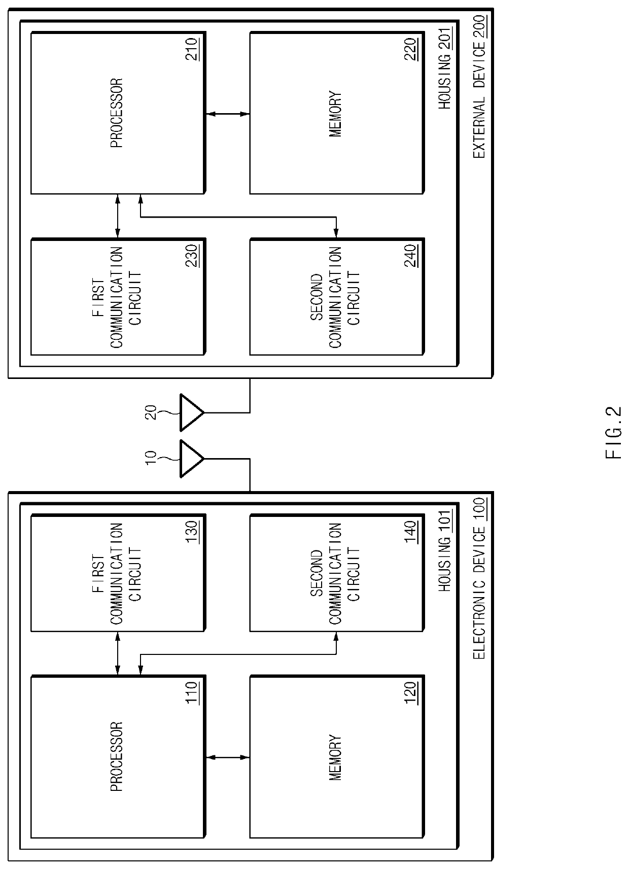
[0033]According to an embodiment, an electronic device 100 may perform peer-to-peer (P2P) communication with an external device 200 (a peer device) in a network environment 1000.

[0034]According to an embodiment, the electronic device 100 may transmit or receive data through wireless communication with the external device 200. The electronic device 100 may also receive power from the external device 200. For example, the electronic device 100 may charge a battery with power received from the external device 200. To this end, the electroni...


PUM


Abstract

Disclosed is an electronic device comprising: a touch screen display; a battery; a plurality of antenna elements arranged in order to perform beamforming for directional wireless communication; a first wireless communication circuit configured to provide, through the antenna elements, first wireless communication having a first coverage; a second wireless communication circuit configured to provide second wireless communication having a second coverage greater than the first coverage; and a processor connected to the display, the battery, the first wireless communication circuit, and the second wireless communication circuit, wherein the processor stores instructions for determining whether an external device is close to the electronic device by using the first wireless communication circuit, enabling at least one antenna element, rather than all the antenna elements, among the plurality of antenna elements, and transmitting data to the external device by using the second wireless communication circuit and the enabled at least one antenna element.

Description

CROSS-REFERENCE TO RELATED APPLICATIONS[0001]This application is a 371 National Stage of International Application No. PCT / KR2018 / 008567, filed Jul. 27, 2018, which claims priority to Korean Patent Application No. 10-2017-0167052, filed Dec. 6, 2017, the disclosures of which are herein incorporated by reference in their entirety.BACKGROUND1. Field[0002]Various embodiments disclosed herein relate to beamforming technology of a wireless communication system.2. Description of Related Art[0003]Wireless communication systems have evolved to support higher data rates to meet ever-increasing traffic demands of wireless data. Recently, 5G systems or Institute of Electrical and Electronics Engineers (IEEE) 802.11ad wireless gigabit alliance (WiGig) systems may support transmission and reception of signals of frequencies in the mmWave band higher than a conventional art to accommodate explosive data traffic, drastically increase a transmission rate per user, accommodate the number of connecte...

Claims


Application Information

Patent Timeline
Patent Type & Authority Patents(United States)
IPC IPC(8): H04B7/06
CPCH04B7/0617H04B5/00H04B7/0491H04B7/0695H04B5/0037
Inventor MIN, HYUN KEELEE, SUN KEYLEE, JUNG HUNLIM, TAE HUNHONG, MIN WHOANAM, CHOUN JONGLEE, SUNG HEE
Owner SAMSUNG ELECTRONICS CO LTD
Why Eureka
Try Eureka