Top combustion stove

a combustion stove and top technology, applied in the direction of combustion types, combustion using lump and pulverulent fuel, furnaces, etc., can solve the problems of significant assembly work and fragile shell structure of the shell, and achieve good or even better combustion performan

Active Publication Date: 2021-10-12
PAUL WURTH SA +1
View PDF22 Cites 0 Cited by
  • Summary
  • Abstract
  • Description
  • Claims
  • Application Information

AI Technical Summary

Benefits of technology

[0005]The disclosure provides a burner configuration for top combustion hot blast stoves which allow overcoming at least some of said known disadvantages, preferably by providing good or even better combustion performance.
[0010]The particular combination of the inclined or even essentially vertically stacked nozzles and tangential gas and air inlet along the circumference of the burner allows for a swirl flow with improved layering and burn off of the combustion media. More importantly, this advantageous combustion conditions are achieved while the structural stability of the burner is drastically increased even if the distribution chambers are arranged within the burner shell compared to known solutions with circumferential horizontal distribution chambers. Indeed, the distribution chambers being inclined or vertical and arranged or distributed along the circumference of the burner, the burner shell comprises continuous inclined or vertical bottom to top wall sections in-between the discrete number of distribution chambers. Furthermore, the wall structure of the burner shell is significantly simplified in terms of brick shapes and assembly work necessary for its construction. As the burner assembly according to the present disclosure does not comprise annular or coaxial distribution chambers, or any other type of interconnection between distribution chambers within the burner shell, the weak inner ring bricks of such known solutions are avoided by the present configuration. A burner as described herein does therefore not require further constructional measures to ensure its structural stability. The height of said air and gas distribution chambers generally represents about 0.3 to about 1, preferably about 0.5 to about 0.9, more preferably about 0.6 to about 0.8 times the height of the burner's cylindrical inner volume, also called combustion chamber or more particularly primary combustion chamber. Depending on the size and intended capacity of the burner, the number of distribution chambers per combustion media will generally be between 1 and 10, preferably between 2 and 4, although this number may exceed 10 if necessary or desired.
[0014]The burning of the combustion media will normally take place within the burner (also called combustion chamber or primary combustion chamber). Due to the configuration of the cylindrical burner and especially the nozzle arrays according to the disclosure, the burning of the media is achieved in the layered swirl flow of the combustion media. By the provision of a frustoconical secondary combustion chamber, the swirl flow of the now normally burned off media continues its revolving along the inner side of the cone shell thus widening its diameter which in turn creates a vertical (axial) partial backflow to the burner (primary combustion chamber). This backflow of hot flue gases promotes an intensive mixing of the combustion media within the burner while allowing keeping the temperature in the burner at values above the kindling point even if and especially when the incoming combustion media are too cold.
[0016]The burner shell and cone shell may be made in one piece or preferably the burner shell is detachably affixed to the stove shell or the cone shell of the frustoconical secondary combustion chamber by flanges or similar means. By attaching the burner by a flange assembly or similar has the particular advantages, that the burner may be taken to the ground for repair and service or simply replaced by a burner of the same specification, or still more advantageously by a burner with different specifications (e.g. of higher capacity / more nozzles, etc.). Such a replacement or upgrade is moreover fast, thereby reducing downtime of the stove or even the plant.
[0018]Preferably, there is provided a circulation zone (typically a cylindrical space or headroom) above the checker bricks for enhancing distribution of the flue gases over the entire cross-section of stove shell. This circulation zone is thus located below the burner assembly as described herein.

Problems solved by technology

A major drawback of these systems is that the structure of the shell is rendered fragile by the existence of the circumferential conducts.
Furthermore these configurations require a huge number of differently shaped bricks and hence significant assembly work.

Method used


Image

  • Top combustion stove
  • Top combustion stove

Examples


Embodiment Construction

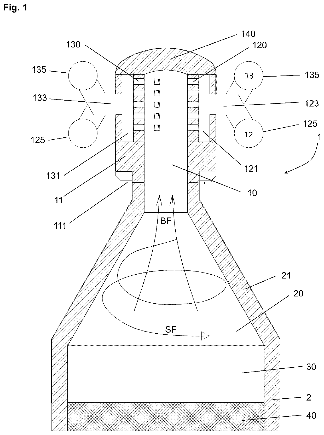
[0025]FIG. 1 shows a cross-section of the upper part of a preferred embodiment of an apparatus for heating air for the operation of regenerators (hot blast stoves) for blast furnaces.

[0026]The burner 10 has a burner shell 11 of circular cross-section and is axially mounted by flange assembly 111 in the upper section of the hot blast stove 1 which comprises a stove shell 2 with a main volume of regenerative checker bricks 40 for storing and exchanging heat and a circulation zone or headroom 30 without checker bricks.

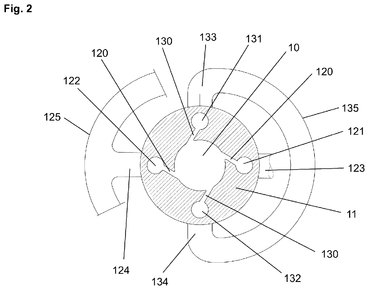
[0027]The burner (or combustion chamber) 10 is closed on top by dome 140 and has separate feeding arrangements for the combustion media air 12 and gas 13. The feeding arrangements include air and gas feeding pipes 125, 135 and air and gas connecting pipes 123, 124, 133, 134 connecting the feeding pipes to the vertical air and gas distribution chambers 121, 122, 131, 132, respectively. Air and gas are fed to the burner 10 through a number of alternating vertical arrays of ...


PUM

PropertyMeasurementUnit
angleaaaaaaaaaa
aperture angleaaaaaaaaaa

Abstract

A burner assembly for top combustion hot blast stove including a burner surrounded by a burner shell, where the burner has a circular cross-section; a number of air nozzles arranged for tangentially feeding air to the burner, the air nozzles being connected to one or more air distribution chambers; a number of gas nozzles arranged for tangentially feeding gas to the burner, the gas nozzles being connected to one or more gas distribution chambers; wherein the air nozzles are arranged in one or more inclined or vertical stacked arrays of air nozzles, each inclined or vertical stacked array being in connection with one inclined or vertical air distribution chamber; the gas nozzles are arranged in one or more inclined or vertical stacked arrays of gas nozzles, each inclined or vertical stacked array being in connection with one inclined or vertical gas distribution chamber; and the inclined or vertical air distribution chamber(s) and the inclined or vertical gas distribution chamber(s) are arranged along the circumference of the burner shell.

Description

TECHNICAL FIELD[0001]The present disclosure generally relates to burner assemblies for hot blast stoves (regenerative air heating devices) for preheating blast in blast furnace operation. More particularly, the disclosure relates to so-called top or dome combustion stoves wherein the burner is arranged on top of the stove.BACKGROUND ART[0002]It is well known within the art of regenerative heating, especially in the art of hot blast stoves, to heat air by passing it through previously heated refractories, generally called checker bricks. The heating of the checker bricks is done by burning top gas from a blast furnace usually enriched with natural gas or coke oven gas in the presence of air, the resulting flue gases being passed through the checker bricks.[0003]The burning of the combustion media (gas and air) is conventionally done in a separate shaft (burner shaft) within the hot blast stove or more recently in the top dome of so-called top or dome combustion hot blast stoves.[0004...

Claims


Application Information

Patent Timeline
Patent Type & Authority Patents(United States)
IPC IPC(8): C21B9/04F23C3/00F23C5/32F23D14/22C21B9/10C21B9/14C21B9/02
CPCC21B9/04C21B9/02C21B9/10C21B9/14F23C3/006F23C5/32F23D14/22
Inventor THALER, STEFANKESSLER, STEFANSCHAUB, ERICSA'DODDIN, HOSSEINLUFT, JURIJ
Owner PAUL WURTH SA
Why Eureka
Try Eureka