Electronic apparatus equipped with flexible boards

a technology of flexible boards and electronic equipment, applied in the field of electronic equipment, can solve the problems of difficult estimation of parasitic components on the wires, loss of flexibility of flexible boards, and bending of flexible boards into main bodies of electronic equipment,

Active Publication Date: 2021-10-12
CANON KK
View PDF12 Cites 0 Cited by
  • Summary
  • Abstract
  • Description
  • Claims
  • Application Information

AI Technical Summary

Benefits of technology

[0005]The present invention provides an electronic apparatus which is capable of achieving ease of incorporating a flexible board, on which ground wires for implementing impedance control are provided, into the electronic apparatus and ease of impedance control at the same time.
[0007]According to the present invention, ease of incorporating a flexible board, on which ground wires for implementing impedance control are provided, into the electronic apparatus and ease of impedance control can be achieved at the same time.

Problems solved by technology

However, if the ground wires for implementing impedance control are provided on one surface of the flexible board, a thickness of the flexible board will increase, causing the flexible board to lose its flexibility.
As a result, incorporating the flexible board in a bent state into a main body of the electronic apparatus will become difficult.
If no ground wires for implementing impedance control are provided on the flexible board, it will be difficult to estimate parasitic components on the wires on the differential transmission paths which are required for impedance control, and as a result, the characteristic impedance cannot be made to coincide with the predetermined value.
Namely, the prior art presents a problem that ease of incorporating the flexible board on which the ground wiring for implementing impedance control into the electronic apparatus and ease of impedance control cannot be achieved at the same time.

Method used


Image

  • Electronic apparatus equipped with flexible boards
  • Electronic apparatus equipped with flexible boards
  • Electronic apparatus equipped with flexible boards

Examples


Embodiment Construction

[0015]An embodiment of the present invention will now be described in detail with reference to the drawings. It should be noted that in the following description of the present embodiment, the present invention is applied to a digital camera which is an electronic apparatus equipped with flexible boards, but the present invention is not limited to the digital camera. For example, the present invention may be applied to apparatuses equipped with flexible boards, such as a smartphone, a tablet terminal, a PC, and a multifunction peripheral.

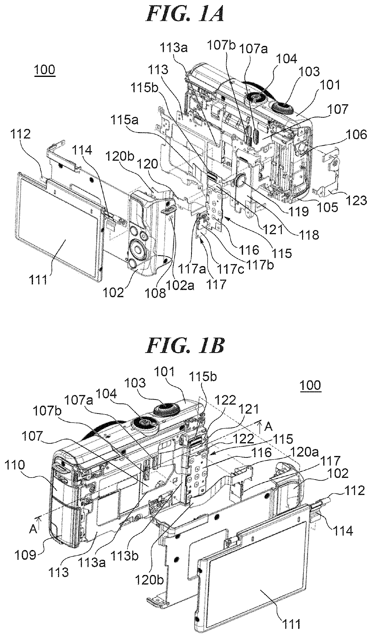
[0016]FIGS. 1A and 1B are exploded perspective views schematically showing an arrangement of the digital camera 100 which is the electronic apparatus according to the embodiment of the present invention. FIG. 1A is an exploded perspective view showing a rear side of the digital camera 100 as seen from the upper right. FIG. 1B is an exploded perspective view showing the rear side of the digital camera 100 as seen from the upper left. It should be not...


PUM


Abstract

An electronic apparatus which achieves ease of incorporating flexible boards into the electronic apparatus and ease of impedance control at the same time. A first flexible board and a second flexible board are placed along a structure having a bent portion and a flat portion. Differential signal wires are wired on one surface of the first flexible board placed between the structure and the second flexible board, and first ground wires for impedance control of the differential signal wires are wired on the other surface and on a rear side of the differential signal wires. Second ground wires for impedance control of the differential signal wires are wired on one surface of the second flexible board the one surface of the first flexible board faces. A wiring density of the first and second ground wires differs between an area along the bent portion and an area along the flat portion.

Description

BACKGROUND OF THE INVENTIONField of the Invention[0001]The present invention relates to an electronic apparatus.Description of the Related Art[0002]With recent improvements in functions of electronic apparatuses, high-speed transmission of digital data is required. To achieve high-speed transmission of digital data, transmission techniques such as LVDS (Low Voltage Differential Signaling) and USB (Universal Serial Bus) are used. LVDS is a high-speed (several hundred Mbps) transmission technique for which circuits and protocols can be relatively freely designed, and it is widely used to transmit signals for an image pickup unit and a liquid crystal display device in digital cameras, cellular phones, and so forth. According to LVDS, signals of small voltage amplitude are transmitted by the differential method, and a characteristic impedance of a pair of differential transmission paths is designed to be a predetermined value determined based on the LVDS standards. Designing to make the...

Claims


Application Information

Patent Timeline
Patent Type & Authority Patents(United States)
IPC IPC(8): H05K1/02H04N5/225H05K1/14
CPCH05K1/025H04N5/2251H05K1/028H05K1/0219H05K1/0245H05K1/147H05K2201/0792H05K2201/09227H05K2201/09672H05K2201/09681H04N23/50H05K1/0253H05K1/0224H05K2201/09345H05K2201/09236H04N23/57
Inventor MOMOSE, HIDEAKI
Owner CANON KK
Why Eureka
Try Eureka