Manufacturing method for tank

a tank and manufacturing method technology, applied in the field of tank manufacturing methods, can solve the problems of voids inside the fiber reinforced resin layer, poor appearance, and decrease in quality, and achieve the effects of reducing quality, reducing appearance, and facilitating heating

Active Publication Date: 2021-10-19
TOYOTA JIDOSHA KK
View PDF7 Cites 0 Cited by
  • Summary
  • Abstract
  • Description
  • Claims
  • Application Information

AI Technical Summary

Benefits of technology

[0007]The present disclosure is accomplished in view of such points, and an object of the present disclosure is to provide a manufacturing method for a tank that can restrain an increase in the volume fraction of fiber of a fiber reinforced resin layer and restrain voids from being formed inside the fiber reinforced resin layer.
[0009]The manufacturing method of the present disclosure includes the first heating step of heating the uncured fiber reinforced resin layer by the low-frequency induction heating so that the thermosetting resin is softened. In a case where the fiber reinforced resin layer is heated by the low-frequency induction heating as such, an inner layer of the fiber reinforced resin layer is easily heated. This allows air and gas in the inner layer of the fiber reinforced resin layer to be easily released outside the fiber reinforced resin layer. As a result, it is possible to restrain voids from being formed inside the fiber reinforced resin layer, thereby making it possible to restrain a poor appearance and a decrease in quality. Note that, when the uncured fiber reinforced resin layer is heated only by the high-frequency induction heating without the low-frequency induction heating after the step of preparing the tank in which the uncured fiber reinforced resin layer is formed on the liner, an outermost layer of the fiber reinforced resin layer hardens, so that the air and the gas in the inner layer are hard to be released outside, thereby resulting in that voids are formed inside the fiber reinforced resin layer.
[0010]Further, the second heating step of heating the softened fiber reinforced resin layer by the high-frequency induction heating so that the fiber reinforced resin layer is hardened is provided after the first heating step. In a case where the fiber reinforced resin layer is heated by the high-frequency induction heating as such, an outer layer (the outermost layer in particular) of the fiber reinforced resin layer is easily heated. Accordingly, the outer layer (the outermost layer in particular) of the fiber reinforced resin layer can be hardened earlier than the inner layer, thereby making it possible to restrain the thermosetting resin from seeping from the outermost layer of the fiber reinforced resin layer. As a result, it is possible to restrain variations in the volume fraction of fiber of the fiber reinforced resin layer and to restrain a strength reduction in the tank due to an increase in the volume fraction of fiber. Note that, in a case where the fiber reinforced resin layer is hardened by heating the fiber reinforced resin layer by the low-frequency induction heating, a timing for the outer layer of the fiber reinforced resin layer to harden delays (the outer layer of the fiber reinforced resin layer does not harden earlier than the inner layer) in comparison with a case where the fiber reinforced resin layer is hardened by heating the fiber reinforced resin layer by the high-frequency induction heating. Consequently, the amount of the thermosetting resin seeping from the outermost layer of the fiber reinforced resin layer increases.
[0011]In the manufacturing method, the first heating step may be switched to the second heating step at a timing when an innermost layer of the fiber reinforced resin layer reaches a hardening starting temperature. When the first heating step is performed by the low-frequency induction heating until the innermost layer of the fiber reinforced resin layer reaches the hardening starting temperature, the air and the gas in the inner layer of the fiber reinforced resin layer can be further easily released outside the fiber reinforced resin layer. Further, by performing the second heating step by the high-frequency induction heating at the timing when the innermost layer of the fiber reinforced resin layer reaches the hardening starting temperature, it is possible to restrain the thermosetting resin from seeping from the outermost layer of the fiber reinforced resin layer. As described above, while the thermosetting resin is restrained from seeping, the air and the gas in the inner layer of the fiber reinforced resin layer can be further easily released.
[0012]In the manufacturing method, in the first heating step, an innermost layer and an outermost layer of the fiber reinforced resin layer may be maintained at a temperature of not less than a melting point of the thermosetting resin but less than a hardening starting temperature for a predetermined time. With this configuration, it is possible to maintain the innermost layer and the outermost layer of the fiber reinforced resin layer in a low viscosity state for the predetermined time, thereby making it possible to surely release the air and the gas in the fiber reinforced resin layer to outside. As a result, it is possible to further restrain voids from being formed inside the fiber reinforced resin layer.
[0013]With the present disclosure, it is possible to provide a manufacturing method for a tank that can restrain an increase in the volume fraction of fiber of a fiber reinforced resin layer and restrain voids from being formed inside the fiber reinforced resin layer.

Problems solved by technology

Further, in a case where air or gas in the fiber reinforced resin layer is hard to be released outside at the time when the fiber reinforced resin layer is hardened by heating, voids are formed inside the fiber reinforced resin layer, thereby causing a poor appearance and a decrease in quality.
Note that, when the uncured fiber reinforced resin layer is heated only by the high-frequency induction heating without the low-frequency induction heating after the step of preparing the tank in which the uncured fiber reinforced resin layer is formed on the liner, an outermost layer of the fiber reinforced resin layer hardens, so that the air and the gas in the inner layer are hard to be released outside, thereby resulting in that voids are formed inside the fiber reinforced resin layer.

Method used


Image

  • Manufacturing method for tank
  • Manufacturing method for tank
  • Manufacturing method for tank

Examples


Embodiment Construction

[0023]With reference to drawings, the following describes a manufacturing method for a high-pressure tank 10 according to an embodiment of the present disclosure. Note that the high-pressure tank 10 is one example of a “tank” in the present disclosure.

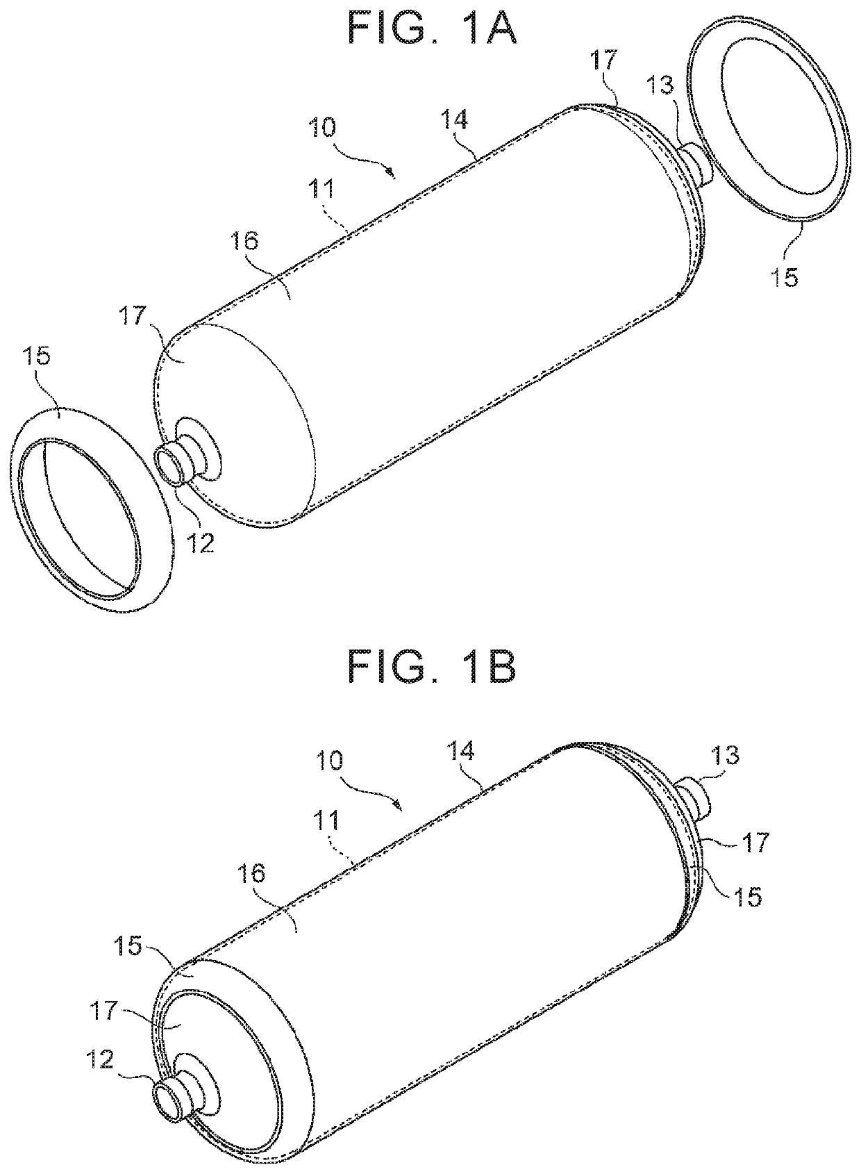
[0024]First described is the configuration of the high-pressure tank 10. As illustrated in FIGS. 1A, 1B, the high-pressure tank 10 is constituted by a liner 11, mouth pieces 12, 13, a reinforced layer (fiber reinforced resin layer) 14 formed on an outer peripheral surface of the liner 11, and a pair of caps 15. The high-pressure tank 10 has such a property that gas hardly passes through the high-pressure tank 10, i.e., a so-called gas barrier property, and is configured such that relatively high-pressure gas such as hydrogen is to be filled inside the high-pressure tank 10.

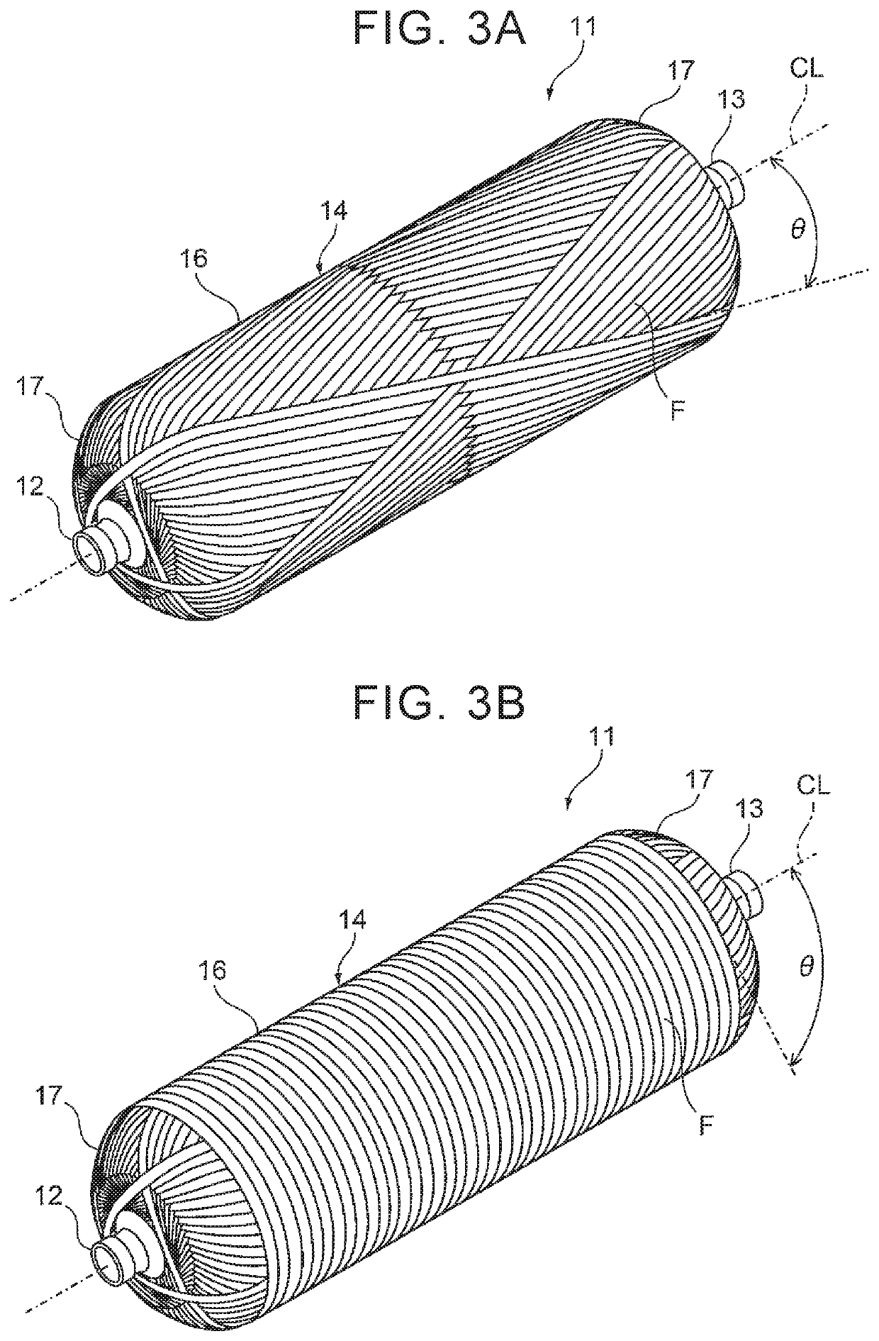
[0025]The liner 11 is constituted by a tubular hollow container and made of resin having a gas barrier property. A resin material of the liner 11 can be, for example...


PUM

PropertyMeasurementUnit
angleaaaaaaaaaa
angleaaaaaaaaaa
frequencyaaaaaaaaaa

Abstract

A manufacturing method for a high-pressure tank is a manufacturing method for a high-pressure tank including a reinforced layer formed such that an electrically conductive fiber bundle impregnated with thermosetting resin is wound around a liner. The manufacturing method includes: a step of preparing the tank in which the uncured reinforced layer is formed on the liner; a first heating step of heating the uncured reinforced layer by low-frequency induction heating so the thermosetting resin is softened; and a second heating step of, after the first heating step, heating the softened reinforced layer by high-frequency induction heating so that the softened reinforced layer is hardened.

Description

INCORPORATION BY REFERENCE[0001]The disclosure of Japanese Patent Application No. 2019-041132 filed on Mar. 7, 2019 including the specification, drawings and abstract is incorporated herein by reference in its entirety.BACKGROUND1. Technical Field[0002]The present disclosure relates to a manufacturing method for a tank including a fiber reinforced resin layer formed such that a fiber bundle is wound around a liner.2. Description of Related Art[0003]In the related art, there has been known a tank including a tank body and a mouth piece portion attached to an open end portion of the tank body in its longitudinal direction, as a high-pressure tank (a high-pressure gas storage container) used for storage and supply of hydrogen or the like. The tank body has a two-layer structure constituted by, for example, a liner in which hydrogen gas is held airtightly, and a fiber reinforced resin layer reinforced by winding a fiber bundle made of carbon fiber reinforced plastics (CFRP) around an ou...

Claims


Application Information

Patent Timeline
Patent Type & Authority Patents(United States)
IPC IPC(8): B29C63/00B29L31/00B29K101/10
CPCB29C63/0069B29C63/0021B29K2101/10B29K2995/0005B29L2031/712F17C1/16F17C1/06B29C70/342B29C70/54B29C65/48F17C2203/0663F17C2203/012F17C2209/2154F17C2209/227F17C2209/232F17C2221/012B29L2031/7156B29C63/10B29C53/005B29C53/602B29C53/66B29C53/845B29C53/822Y02E60/32
Inventor HATTA, KEN
Owner TOYOTA JIDOSHA KK
Why Eureka
Try Eureka