Positioning element with recesses for a guide vane arrangement

a technology of positioning elements and recesses, which is applied in the direction of blade accessories, engine components, stators, etc., can solve the problems of strong wear and tear of sealing elements, and achieve the effect of lessening the recording

Active Publication Date: 2021-10-26
MTU AERO ENGINES GMBH
View PDF16 Cites 0 Cited by
  • Summary
  • Abstract
  • Description
  • Claims
  • Application Information

AI Technical Summary

Benefits of technology

[0004]The object of the invention is to provide a positioning element in which the cording effect is lessened.
[0005]For this, it is proposed that at least one recess is provided in the base section, which is arranged between two neighboring uptake openings and runs from inside to outside at least in the radial direction. The providing of such recesses makes it possible for the positioning element to have a shorter effective radial height in the region of the recess, which is acted upon by the temperature gradient, and which exerts an influence on the strain in the positioning element. When such recesses are provided at several places along the periphery between respective uptake openings, the cording effect can be influenced, since the deformations occurring are less than in the case of a continuous positioning element without recesses. The recesses in the positioning element also lead to a reduced bending stiffness of the positioning element. Besides the thermal effects, the cording effect is also influenced by the ratio of the bending stiffnesses of positioning element and seal carrier. It is advantageous in this case for the positioning element to be “softer” or less stiff, because then the cording effect is less. Moreover, with a less bending-stiff positioning element, a stiffer seal carrier can counteract the constriction of the positioning element.
[0007]A reduction of the cording effect and thus of constrictions at the positioning element also leads to a reduction of local inflows at a parting plane of the semicircularly shaped base sections. Due to fewer constrictions, the formation of gaps and leaks can also be avoided, which has a positive impact on the efficiency and the surge limit, especially because leaks at the sealing elements can be reduced.
[0008]Moreover, thanks to the smaller inflows, a lower load on the sealing elements can also be achieved, especially at rotor sealing fins and their coating. This leads to an improved or longer durability, so that the maintenance and repair effort and expense can be reduced.

Problems solved by technology

This has the consequence, in particular, that the seal carrier or its sealing elements come into contact with sealing fins rotating relative to them, so that strong wear and tear occurs on the sealing elements.

Method used


Image

  • Positioning element with recesses for a guide vane arrangement
  • Positioning element with recesses for a guide vane arrangement
  • Positioning element with recesses for a guide vane arrangement

Examples


Embodiment Construction

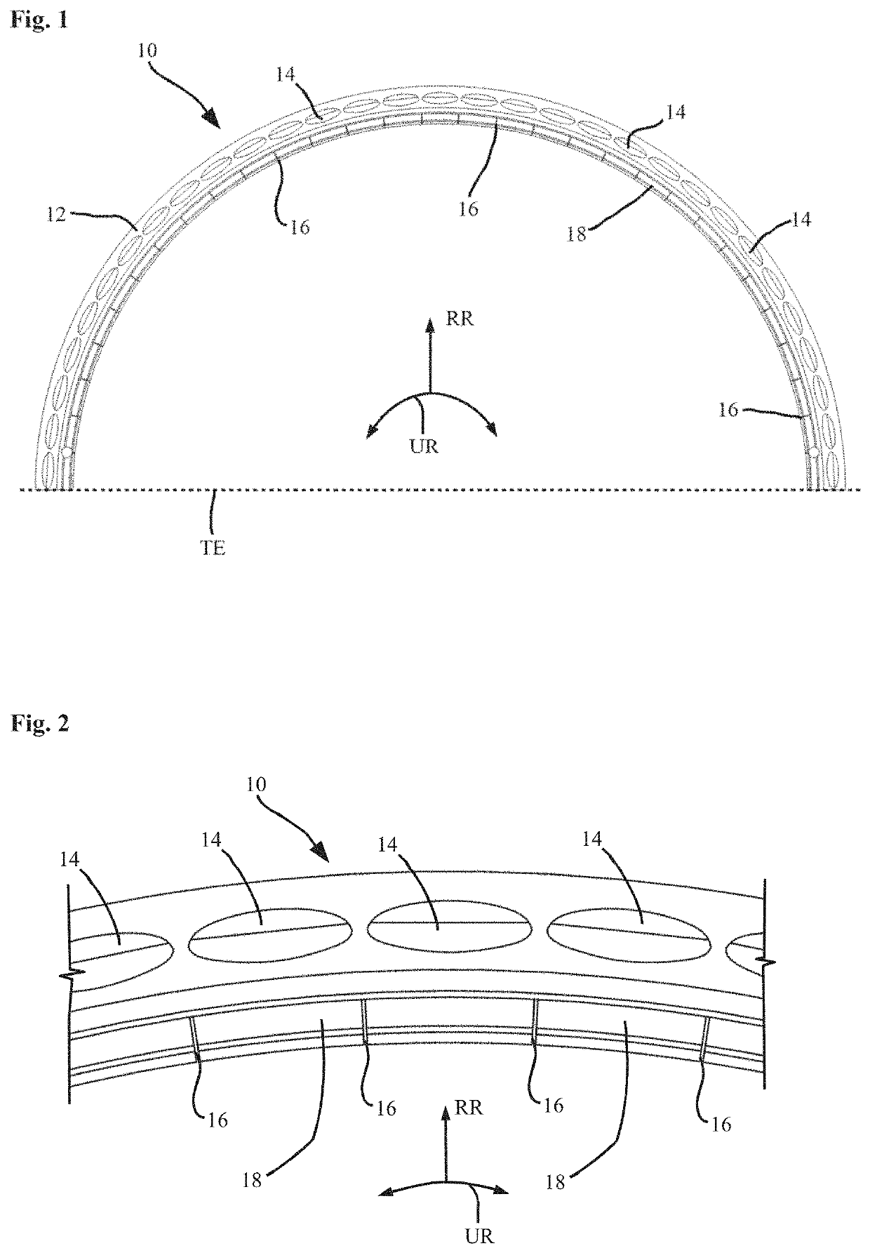
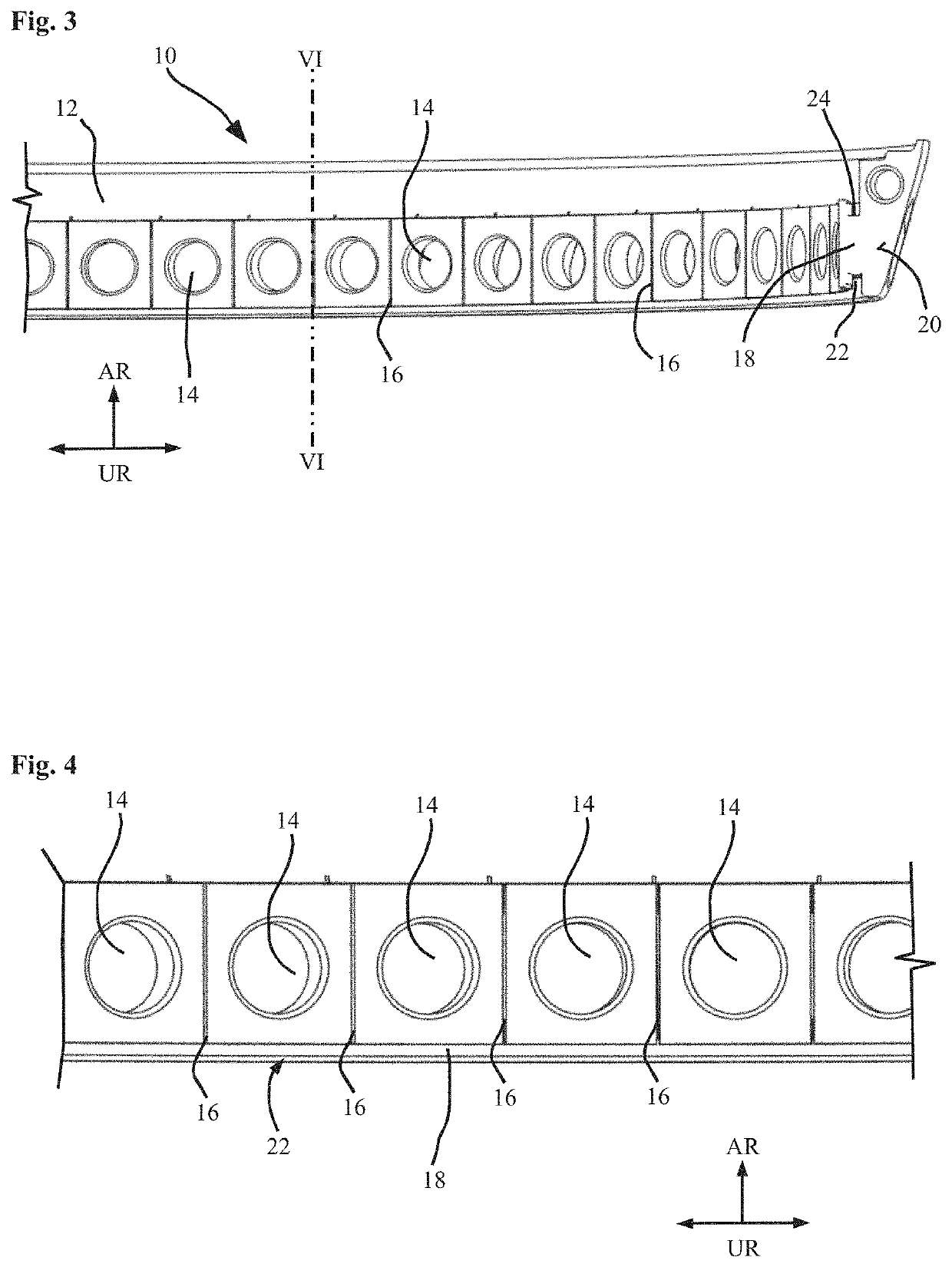
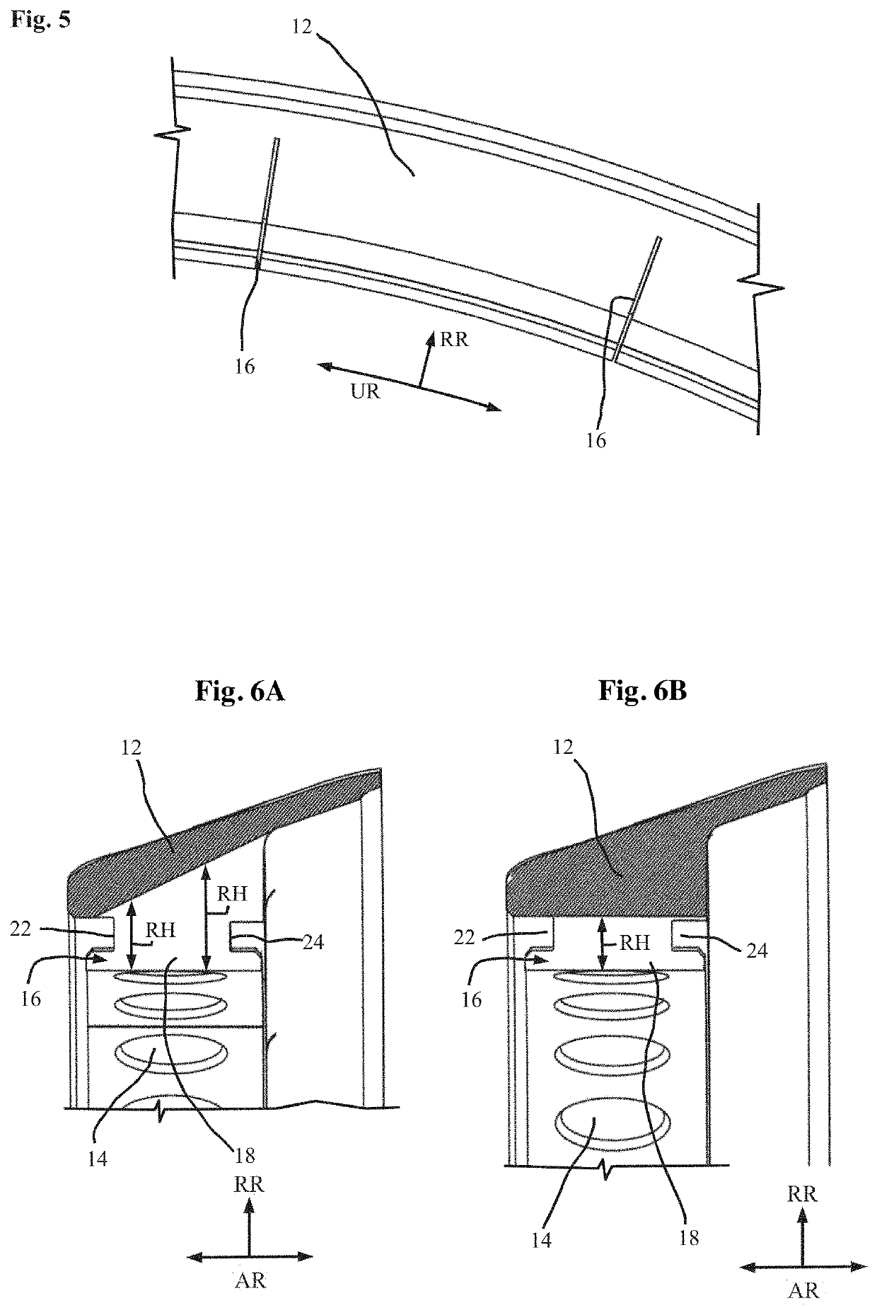
[0031]FIG. 1 shows in a simplified schematic top view in the axial direction a first embodiment of a positioning element 10 and FIG. 2 shows a magnified section of the positioning element 10. As is evident from these figures, the positioning element 10 comprises a base section 12, which his curved in a semicircle. In the base section 12 there are provided a plurality of uptake openings 14 arranged next to one another in the peripheral direction UR. The uptake openings 14 serve in particular to accommodate guide vanes, not shown here. Respective recesses 16 are visible in the peripheral direction UR between two neighboring uptake openings 14. These recesses 16 extend in the radial direction RR from the inside to the outside. In the region of the broken line TE (FIG. 1) the so-called parting plane is indicated. In the region of this parting plane, two semicircular base sections 12 lie against one another, so that a complete circular positioning element 10 can be formed. The base secti...


PUM


Abstract

The invention relates to a positioning element for a guide vane arrangement of a guide vane stage of a gas turbine, with at least one base section curved in the peripheral direction; a plurality of uptake openings arranged next to each other in the peripheral direction on the base section, whose aperture axis runs substantially in the radial direction and which are designed to take up a respective radially inner guide vane section; a coupling section provided on the base section, which is or can be coupled to a seal carrier of a seal arrangement. According to the invention, it is proposed that at least one recess is provided in the base section, which is arranged between two neighboring uptake openings and runs from inside to outside at least in the radial direction.

Description

BACKGROUND OF THE INVENTION[0001]The present invention relates to a positioning element for a guide vane arrangement of a guide vane stage of a gas turbine, with at least one base section curved in the peripheral direction; a plurality of uptake openings that are arranged next to each other in the peripheral direction on the base section and whose aperture axis runs substantially in the radial direction and that are designed to accommodate a respective radially inner guide vane section; a coupling section provided on the base section, which is coupled or can be coupled to a seal carrier of a seal arrangement.[0002]Directional indications such as “axially” or “axial” and “radially” or “radial” and “peripheral” should basically be understood as referring to the machine axis of the gas turbine, unless otherwise indicated explicitly or implicitly from the context. Such a guide vane stage may be arranged in the region of a compressor or in the region of the turbine. The feature of a coup...

Claims


Application Information

Patent Timeline
Patent Type & Authority Patents(United States)
IPC IPC(8): F01D25/24F01D9/04F01D5/30
CPCF01D25/246F01D5/303F01D9/041F01D9/042F05D2230/644F05D2240/14F05D2250/141F05D2260/941
Inventor ALBERS, LOTHARBOECK, ALEXANDER
Owner MTU AERO ENGINES GMBH
Why Eureka
Try Eureka