Support bracket assembly and method

a technology of support brackets and brackets, which is applied in the direction of structural elements, building components, covering/linings, etc., can solve the problems of excess mortar falling the air gap does not provide space to remove excess mortar with a trowel or provide space, and the excess mortar in the inside to fall between the masonry veneer and the insulation,

Active Publication Date: 2021-11-02
FERO CORP
View PDF86 Cites 2 Cited by
  • Summary
  • Abstract
  • Description
  • Claims
  • Application Information

AI Technical Summary

Problems solved by technology

By contrast, in a contemporary masonry veneer wall, the air gap does not provide room to remove excess mortar with a trowel or provide space to use a jointer afterward.
There is a tendency for excess mortar in the inside to fall between the masonry veneer and the insulation.
This is not generally helpful, since the mortar that falls downward may block weep holes in the brick or may otherwise obstruct drainage passageways.
Further, when a shell angle is used, moisture trapped by fallen mortar on the shelf angle may tend to cause rusting.
If the rust leaks, it may then yield staining visible on the outside of the wall.
Furthermore, there is a variety of non-standard circumstances in which more specialized installation arrangements may be required.
In some circumstances the rearward side of the structural web may not be easily accessible, as when the structural member is a closed-periphery hollow structural section.
Anchor embedments in concrete in which either the connection is in tension, or the connection is being twisted, or both, may tend not to be optimal, and this non-optimality may be heightened where the embedment is in relatively close proximity to rebar.

Method used


Image

  • Support bracket assembly and method
  • Support bracket assembly and method
  • Support bracket assembly and method

Examples


Embodiment Construction

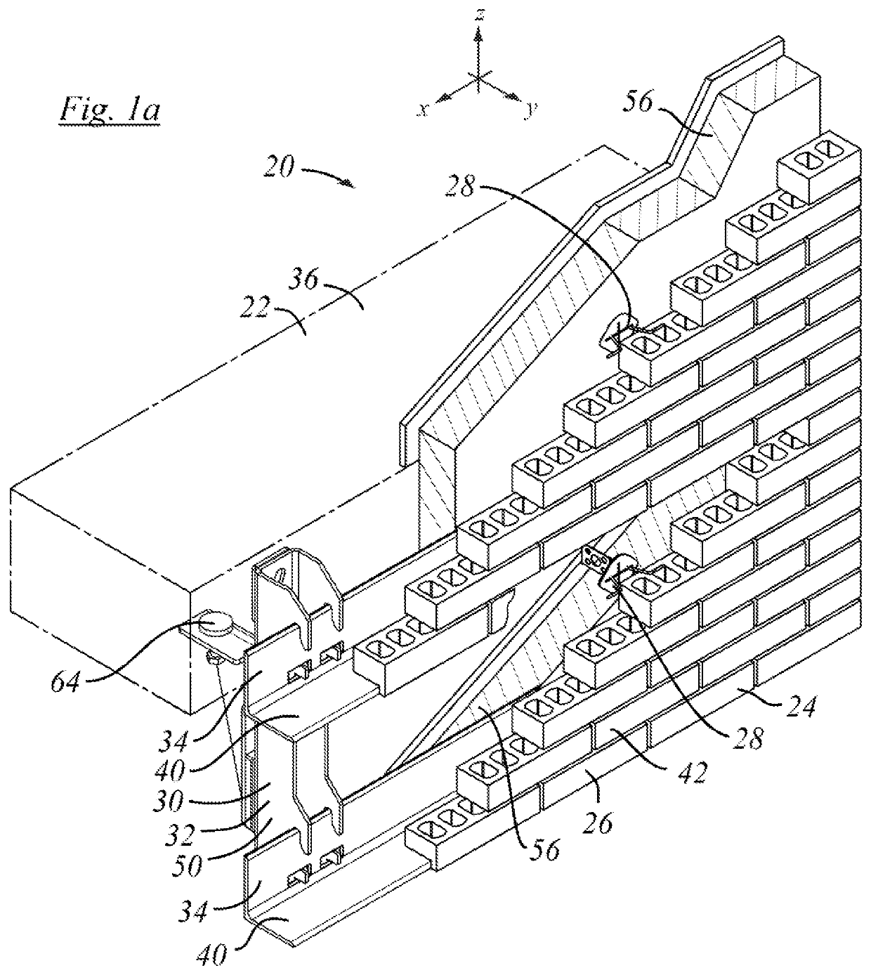
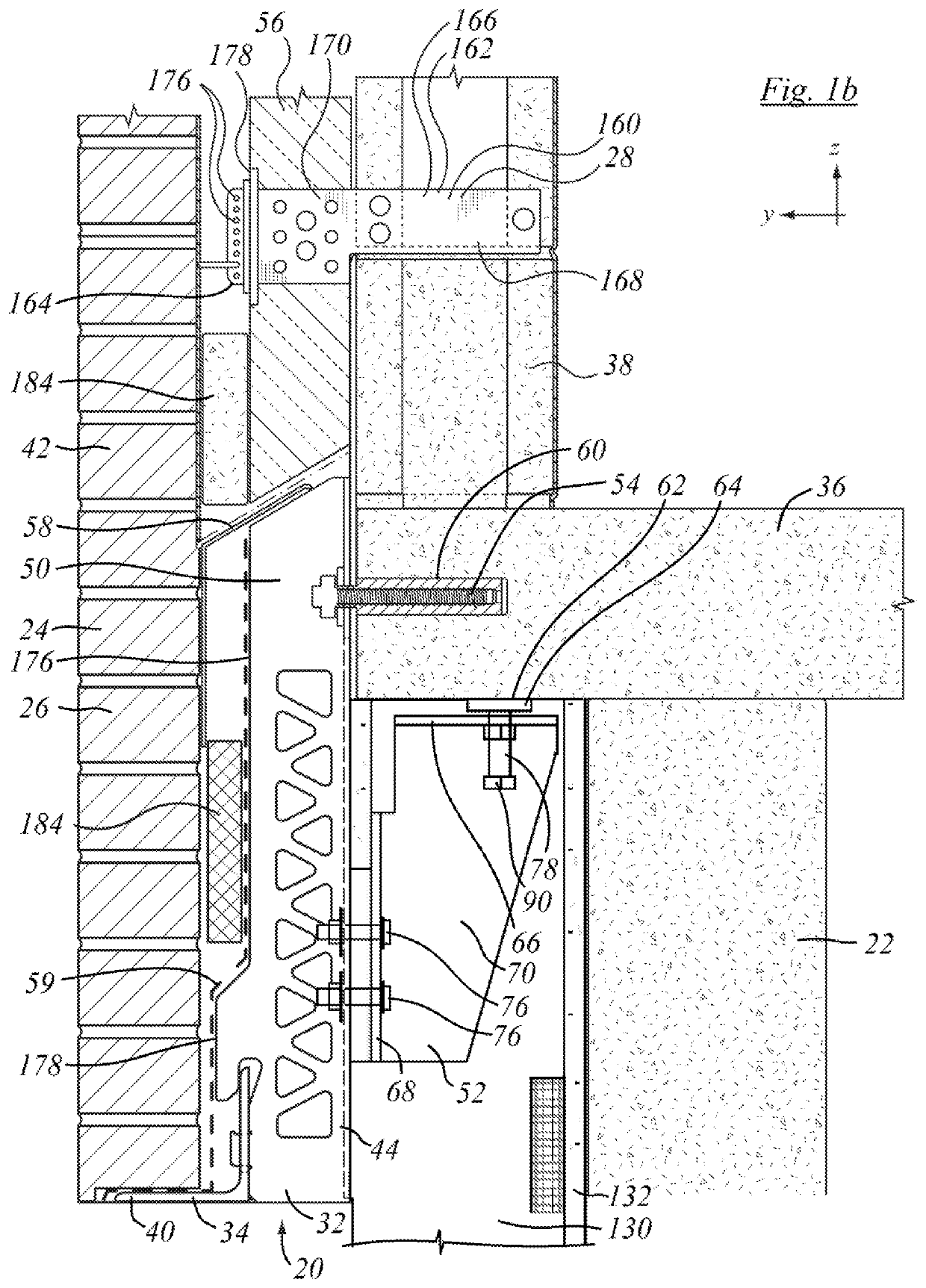
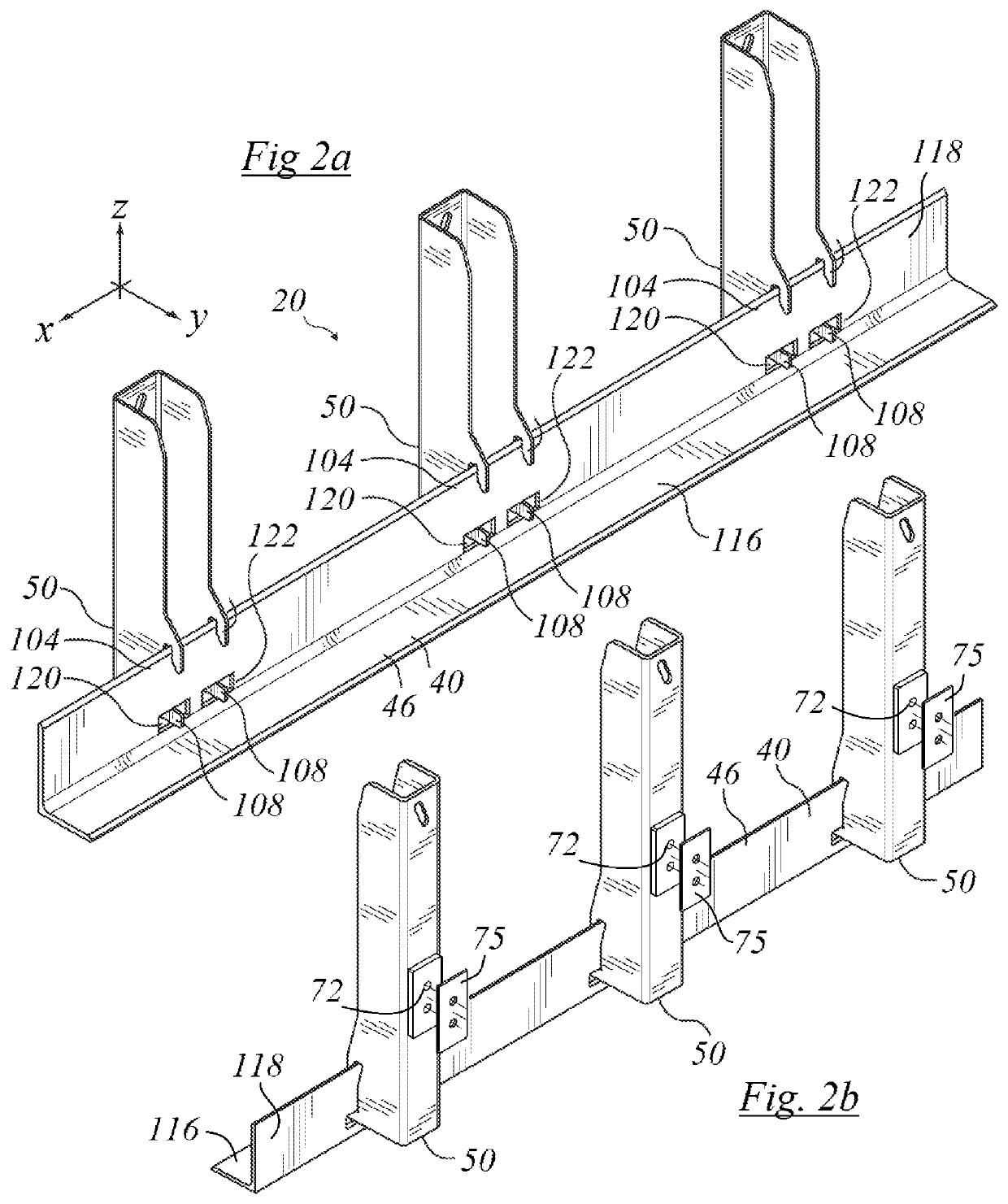
[0026]The description that follows, and the embodiments described, are provided by way of illustration of an example, or examples, of embodiments of the principles of the invention. These examples are provided for the purposes of explanation, and not of limitation, of those principles and of the invention. In the description, like parts are marked throughout the specification and the drawings with the same respective reference numerals. The drawings may be taken as being to scale, or generally proportionate, unless indicated otherwise.

[0027]The terminology used in this specification is thought to be consistent with the customary and ordinary meanings of those terms as they would be understood by a person of ordinary skill in the art in North America. The Applicant expressly excludes all interpretations that are inconsistent with this specification. In this description the term “shelf angle” is a term of art in the field of masonry installation. It refers to an angle iron having a ho...


PUM


Abstract

A support assembly for mounting masonry veneer to supporting wall structure has a first shelf angle, a second shelf angle, and a first shelf angle mounting bracket. Each shelf angle mounting bracket has an upwardly extending back that mounts to the supporting wall structure, and a web extending forwardly away from the wall structure. The web has at least a first shelf angle mounting seats formed in a lower region thereof that hangs downwardly of a vertical load shear transfer connection. A brace is mounted to the bracket. The brace underhangs the cantilevered supporting structure, and provides a moment reaction. The brace has a non-intrusive interface with the supporting structure. That interface may be in compression and the brace may act as a strut. The brace may be thermally isolated from the bracket. The brace may fit within the space envelope of a stud wall.

Description

FIELD OF INVENTION[0001]This specification relates to structural materials for use in the construction of buildings, and, in one particular context, to support structure external veneer components.BACKGROUND OF THE INVENTION[0002]In former times, brick stone, or other masonry walls were load bearing structures. In contemporary building structures bricks, or other masonry elements, or other visible finished surface elements, are rarely load-bearing and tend more often to be employed as surface cladding on the exterior face of load-bearing structure. When mounting face brick or stone veneer on the face of a wall structure, it is common to support the first row of bricks, or stone, or veneer on a steel support. In the art, the steel support for the masonry veneer may be termed a “shelf angle”. The “shelf angle” extends outward from the wall structure, and runs along, or has a major dimension extending in, a direction that is generally horizontal and cross-wise to the wall. The steel su...

Claims


Application Information

Patent Timeline
Patent Type & Authority Patents(United States)
IPC IPC(8): E04C3/00E04F13/08E04F13/14
CPCE04F13/0805E04F13/0862E04F13/14E04F13/0821E04F13/142
Inventor HATZINIKOLAS, MICHAEL
Owner FERO CORP
Why Eureka
Try Eureka