Reciprocating pump

a pump and reciprocating technology, applied in the direction of piston pumps, positive displacement liquid engines, instruments, etc., can solve the problems of not always easy to achieve good diabetes management, heavy and cumbersome use, and is typically more expensive than other methods of treatment, so as to reduce the size of the drug reservoir, and increase the drug concentration in the reservoir.

Active Publication Date: 2021-11-16
BECTON DICKINSON & CO
View PDF81 Cites 0 Cited by
  • Summary
  • Abstract
  • Description
  • Claims
  • Application Information

AI Technical Summary

Benefits of technology

[0013]An advantage of a pump according to an embodiment of the present invention is that very small and precise amounts of liquid medicament can be pumped per revolution of the piston or a diaphragm. This enables small liquid dosages to be injected very precisely, and as a result, higher drug concentration in the reservoir becomes possible. Higher drug concentration further reduces the size of the drug reservoir and prolongs the replacement interval between reservoir cartridges. Due to the compact size of a pump according to an embodiment of the present invention, it may be employed in a wearable patch pump or otherwise positioned close to the point of injection.

Problems solved by technology

It is not always easy, however, to achieve good diabetes management, while balancing other life demands and circumstances.
A major disadvantage of existing insulin pumps is that, in spite of their portability, they include multiple components and can be heavy and cumbersome to use.
They are also typically more expensive than other methods of treatment.
From a lifestyle standpoint, the conventional pump with its associated tubing and infusion set can be inconvenient and bothersome for the user.

Method used


Image

  • Reciprocating pump
  • Reciprocating pump
  • Reciprocating pump

Examples


first embodiment

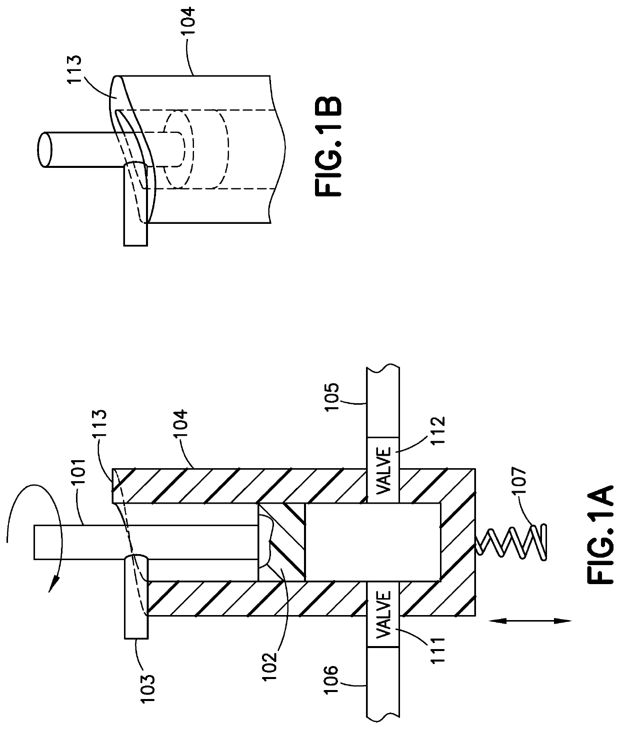
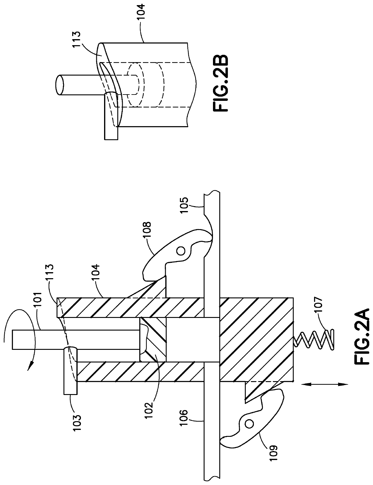
[0024]As shown in FIGS. 1A and 1B, a pump according to the present invention is illustrated in cross-sectional and partial upper perspective views. The pump comprises a chamber 104 within which a piston 102 is rotatably received. A shaft or piston rod 101 is rigidly connected to the piston 102. A post 103 is rigidly connected to the shaft 101 and serves as a cam follower for contacting a cam surface 113 that extends around the top edge of the chamber 104. In this embodiment, the piston 102 only rotates inside the chamber 104 and does not engage in any movement in the axial direction of the chamber 104. Instead, it is the chamber 104 that reciprocates axially as the rotation of the shaft 101 is translated to axial motion of the chamber 104 by virtue of the cam surface 113 and the post 103. This design is mechanically less complicated than conventional designs because it does not require a rotating linkage that is capable of axial sliding. This design also increases reliability and re...

third embodiment

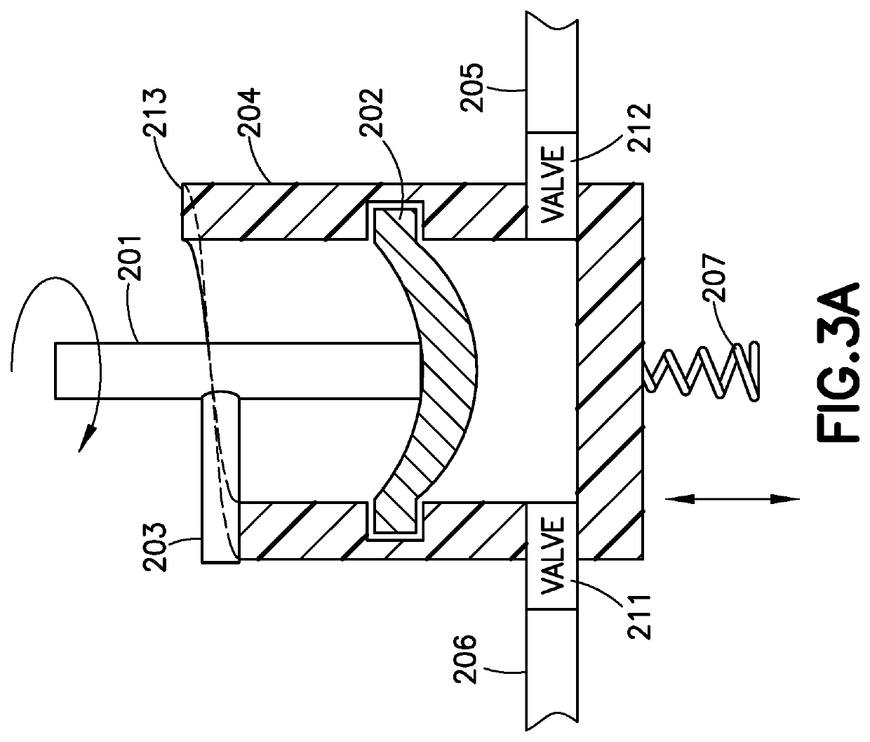
[0030]In FIGS. 3A-3C, a pump according to the present invention is illustrated in cross-sectional and partial upper perspective views. The pump comprises a chamber 204 within which a flexible diaphragm 202 is rotatably received. A shaft 201 is rigidly connected to the diaphragm 202. A post 203 is rigidly connected to the shaft 201. Analogous to the previous embodiment, the diaphragm 202 only rotates inside the chamber 204 and does not engage in movement in the axial direction. The chamber 204 comprises an inlet 205, an outlet 206, an inlet valve 212 and an outlet valve 211. A biasing means 207 such as a coil spring acts on the chamber 204 for applying a biasing force on the chamber 204 in an axial direction of the chamber 204. The biasing means 207 maintains constant contact between the post 203 and the cam surface 213. The axial translation of the chamber 204 is coordinated with the opening and closing of the inlet valve 212 and outlet valve 211. The valves 211 and 212 may be self-...


PUM


Abstract

A pump suitable for use in a wearable medical device, such as a patch pump, comprises an axially translatable chamber with an inlet and an outlet, a piston or a diaphragm rotatably received in the chamber, a first valve between the inlet and the chamber, a second valve between the outlet and the chamber, a cam affixed to the chamber, a follower affixed to the piston and in contact with the cam for axially translating the chamber, and a biasing means acting on the chamber for applying a force on the chamber in an axial direction of the chamber to maintain such contact.

Description

FIELD OF THE INVENTION[0001]The present invention relates generally to a compact, precise, reliable and low cost pump suitable for subcutaneous delivery of a liquid pharmaceutical product. More particularly, embodiments of the present invention relate to a pump with a piston or diaphragm that undergoes a rotational motion. The pharmaceutical product to be delivered may be insulin for diabetic patients.BACKGROUND OF THE INVENTION[0002]Diabetes is a group of diseases marked by high levels of blood glucose resulting from defects in insulin production, insulin action, or both. There are 23.6 million people in the United States, or 8% of the population, who have diabetes. The total prevalence of diabetes has increased 13.5% since the 2005-2007 time period. Diabetes can lead to serious complications and premature death, but there are well-known products available for people with diabetes to help control the disease and lower the risk of complications.[0003]Treatment options for people wit...

Claims


Application Information

Patent Timeline
Patent Type & Authority Patents(United States)
IPC IPC(8): F04B7/00F04B49/06A61M5/145A61M5/168A61M5/142
CPCF04B7/0061A61M5/1452A61M5/14248A61M5/14586A61M5/16881F04B49/06A61M5/14216A61M5/14224A61M39/24F04B53/22F04B43/02
Inventor GYORY, J. RICHARD
Owner BECTON DICKINSON & CO
Why Eureka
Try Eureka