Mobile microscope assembly

a microscope and mobile technology, applied in the field of microscope assembly, can solve the problems of a large number of users using complex software in the central data processing system, and achieve the effect of simple design, high-quality processing and logging

Active Publication Date: 2021-11-16
OCULYZE GMBH
View PDF35 Cites 0 Cited by
  • Summary
  • Abstract
  • Description
  • Claims
  • Application Information

AI Technical Summary

Benefits of technology

[0011]It is an object of the invention to provide a device of the above mentioned kind, which is small, inexpensive, has a simple design and can be used mobile on-site and, at the same time, allows for high-quality processing and logging.
[0015]A particularly inexpensive, compact and portable microscope assembly is achieved with such an assembly. In particular, the lens can be a lens with a diameter of under 5 mm, preferably under 2 mm. A strong curvature with large magnification is hereby achieved. A particularly preferred embodiment of the invention uses a ball lens with a diameter of 1 mm. Alternatively, an even smaller lens with a diameter of 0.5 mm may also be used. In particular, the detector plane of the camera is adapted to be fixed in the imaging plane or slightly behind it.
[0016]Using a simple arrangement, a high degree of magnification is achieved with this type of lens assembly. The recorded image is transmitted from the mobile end device to a central data processor. This is advantageous in that regardless of the performance capacity of the mobile end device, large computing and storage capacities can be used. This central data processing system can be set up at an entirely different location. It is not influenced by the local production process. Notably, the central data processing system can employ complex software used by a great number of users. This way, investment costs are low. The software, in particular, can serve to automate processing steps. The user then needs a correspondingly lower level of expertise than if he or she carries out the processing on-site by him- or herself. The user then promptly obtains the desired result and does not need to manually process the sample. The use of a central data processing system further enables correction of blurred edge ranges of the images. Such blurred edge ranges are very pronounced for ball lenses and comparable lenses with small diameter. Since the cause of the blur is well defined and the same for all images, it is easily corrected with a suitable software.
[0017]In a particularly simple modification of the invention, the camera receiving unit is formed by a slot adapted to receive a smartphone or another flat mobile end device. The mobile end device is equipped with its own camera. Examples of such mobile end devices with cameras are smartphones and tablet computers. The camera is positioned directly underneath the lens assembly. The slot thereby serves as a lead so that no complicated alignment is necessary. Preferably, adjustment means for adjusting the camera position are provided. Then, the slot can be adapted to the dimensions of the mobile end device or the position of the camera. An adjustment does not need to be performed for every image of the same camera, but only upon changing the camera. Accordingly, it is possible to record the images without much effort.
[0032]In particular, it can be provided that the camera is integrated into the mobile end device and that the mobile end device is fixed for the recording in a defined position relative to the microscope. Such fixing may be effected, for example, by means of a slot into which the mobile end device is inserted as far as it will go. The slot serves as a lead so that lateral shifting is avoided. However, it is also possible to use a fixing of a different kind, such as with clasps or the like.

Problems solved by technology

Notably, the central data processing system can employ complex software used by a great number of users.

Method used


Image

  • Mobile microscope assembly
  • Mobile microscope assembly
  • Mobile microscope assembly

Examples


Embodiment Construction

1. Embodiment (FIGS. 1 to 4) Recording with a Smartphone

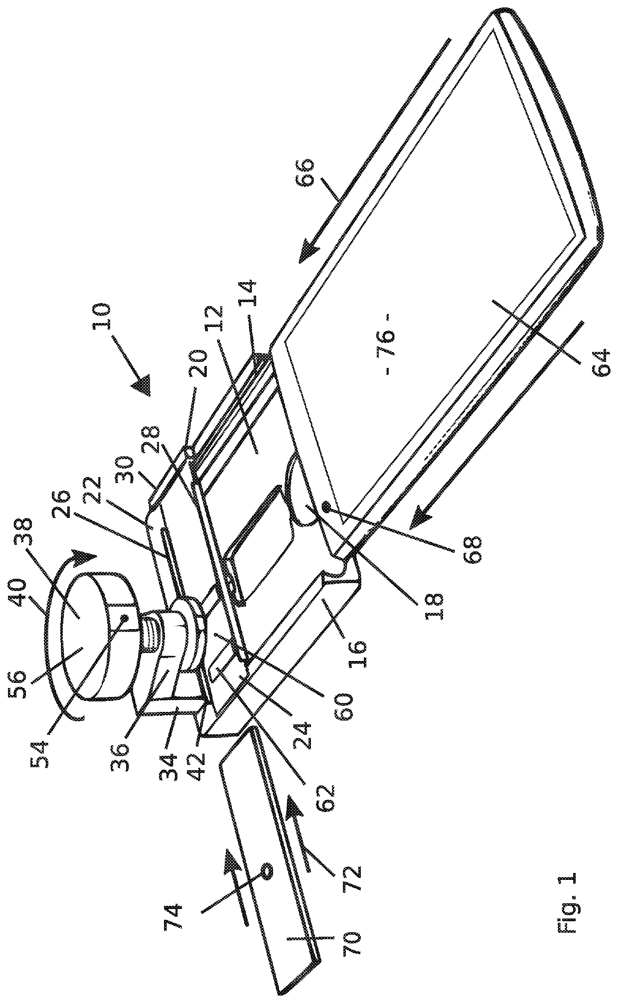
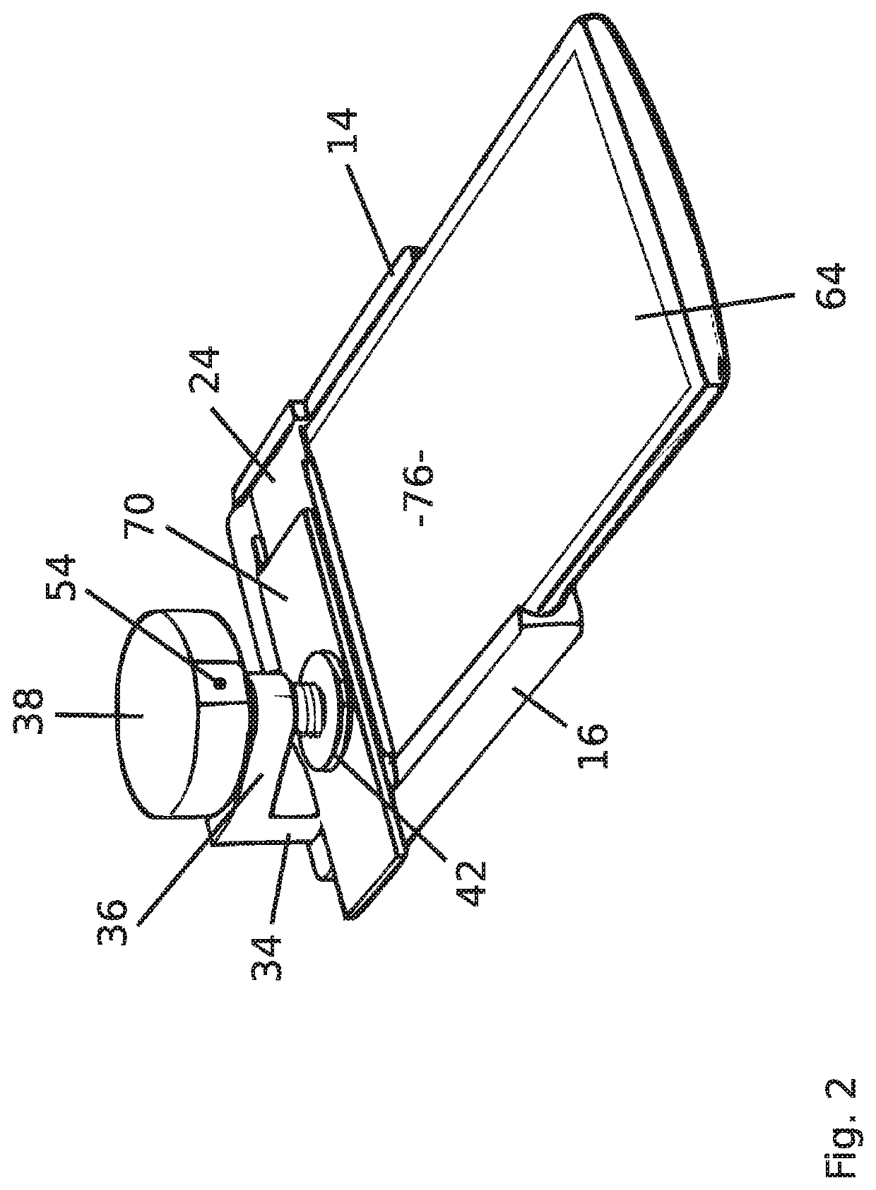
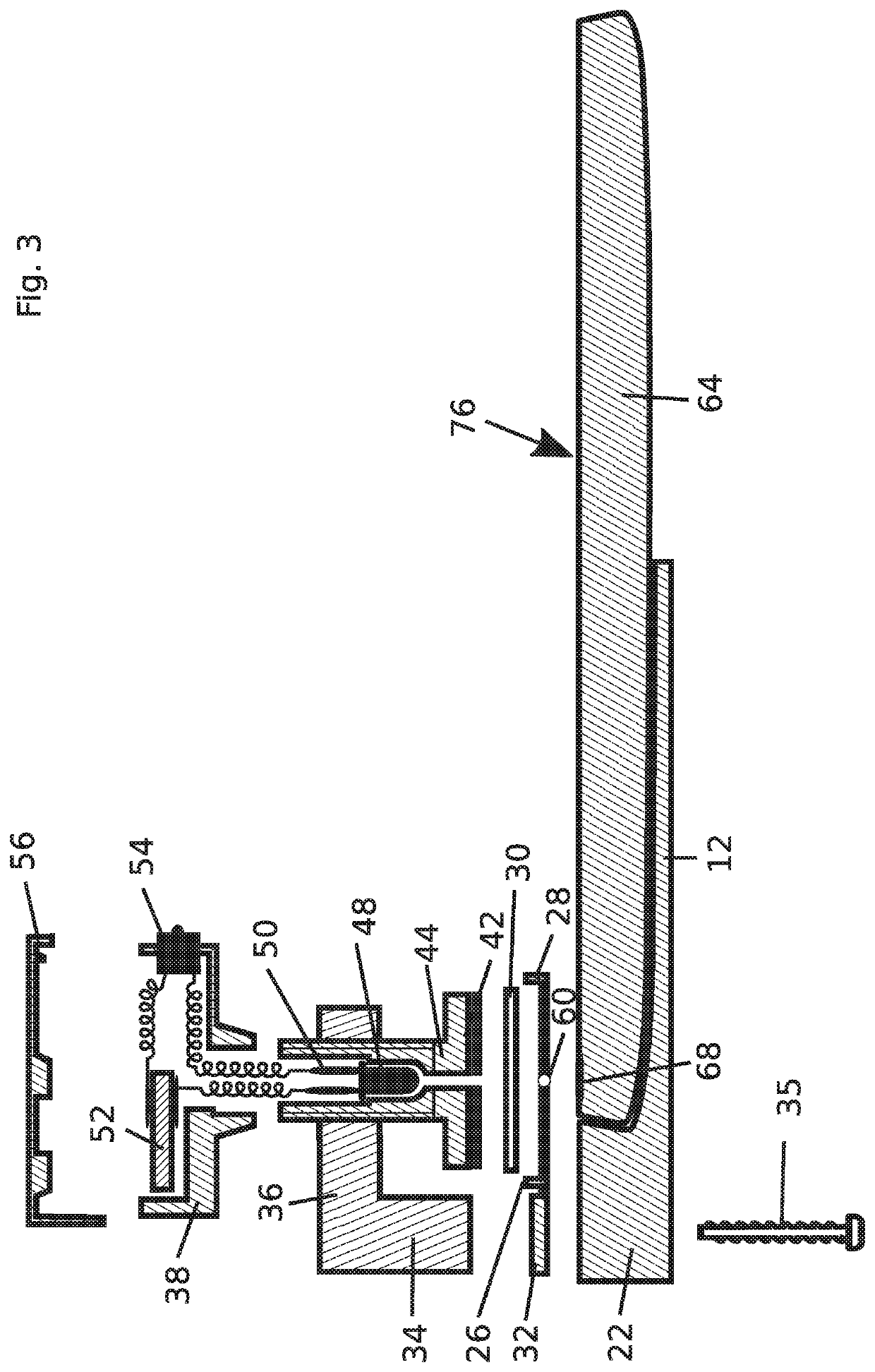
[0061]FIG. 1 shows a microscope attachment generally designated with numeral 10. In the present embodiment the microscope attachment consists of plastic material. An alternative embodiment uses a microscope attachment made of metal, in particular, stainless steel. The microscope attachment 10 has a flat slot 12 with rail-shaped side walls 14 and 16. A depression 18 is provided in the bottom part of the slot 12. In the depression 18 there is an NFC tag (not shown). The upper side of the slot 12 is open. The rear area of the slot 12 in FIG. 1 is closed and forms a stop with a rear wall 22.

[0062]A bracket 20 is mounted on the upper side of the slot 12. However, it is also possible to produce the bracket 20 as a separate component and then fasten or weld it thereto with suitable glue or fastening elements. The bracket 20 sits on the side walls 14 and 16 at the rear end of the slot 12. It has a planar, rectangular base plate 24 with...


PUM


Abstract

A microscope assembly can be used during microbiological processes. The microscope assembly includes a lens assembly for magnified imaging of an object range in an imaging plane along an optical path; a sample receiving unit for a sample arranged in the object range; and a camera receiving unit for receiving a camera in a range of the imaging plane the camera adapted to generate a digital image of the sample; where the lens assembly is a ball lens, a halved ball lens, or a lens in the form of a rotational spheroid; and the camera receiving unit is adapted to receive a customary mobile end device equipped with a camera or a camera cooperating with a mobile end device.

Description

[0001]This application is a National Stage entry under § 371 of International Application No. PCT / EP2017 / 053634, filed on Feb. 17, 2017, and claims priority to German Patent Application No. 10 2016 102 867.3, filed on Feb. 18, 2016.TECHNICAL FIELD[0002]The invention relates to a microscope assembly comprising (a) a lens assembly for magnified imaging of an object range in an imaging plane; (b) a sample receiving unit for a sample arranged in the object range; and (c) a camera receiving unit for a camera arranged in the range of the imaging plane of the lens assembly for generating a digital image.[0003]A lens assembly may be understood as a single lens but also as an assembly of several lenses. In the case of microscopes, an image of the object range is generated in an imaging plane, which is magnified several times with the lens assembly. When a sample is inserted into the object range, the sample is enlarged imaged in an imaging plane of the lens assembly. Known microscopes have a...

Claims


Application Information

Patent Timeline
Patent Type & Authority Patents(United States)
IPC IPC(8): G02B21/00G02B21/02G02B21/36G06K9/00G06T5/00H04N5/225H04N5/232H04M1/02G03B17/56
CPCG02B21/0008G02B21/02G02B21/362G06K9/0014G06K9/00147G06T5/006H04N5/2253H04N5/23229G02B21/361G03B17/565G06T2207/10056H04M1/0264G06V20/695G06V20/698H04N23/54H04N23/80
Inventor SCHULZE, KATJA
Owner OCULYZE GMBH
Why Eureka
Try Eureka