
Electronic device for controlling voltage conversion mode and operation method thereof

a voltage conversion mode and electronic device technology, applied in the direction of process and machine control, multiple modulation transmitter/receiver arrangement, instruments, etc., can solve the problems of relatively limited supply of relatively high load current, and low conversion efficiency of pwm mode, etc., to achieve low conversion efficiency, reduced transmission rate (a throughput), and increased consumption current

Active Publication Date: 2021-11-16
SAMSUNG ELECTRONICS CO LTD
View PDF15 Cites 0 Cited by
  • Summary
  • Abstract
  • Description
  • Claims
  • Application Information

AI Technical Summary

Benefits of technology

This patent is about a way to improve the performance of electronic devices that use a DC-DC converter. When using a PFM mode, noise from the converter can affect communication performance, leading to slow transmission rates. Using a PWM mode can improve conversion efficiency, but will increase consumed currents. The disclosed invention provides a way to balance these two modes, increasing communication efficiency while reducing current consumption.

Problems solved by technology

However, the supply of a relatively high load current is limited, and noise may relatively occur much.
However, a PWM mode has relatively low conversion efficiency and may thus be disadvantageous in terms of consumed currents.
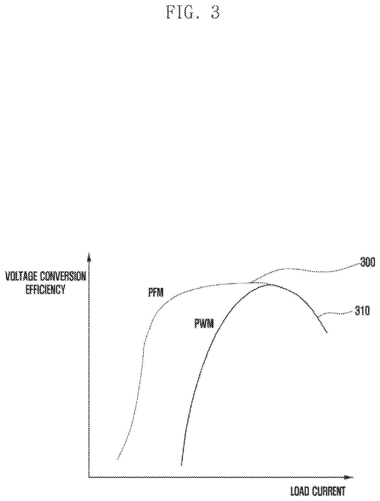
In a case that an electronic device configures a voltage conversion mode of a DC-DC converter to a PFM mode, noise occurring from the DC-DC converter affects communication performance, and thus a transmission rate (a throughput) may decrease.
In a case that an electronic device configures a voltage conversion mode of a DC-DC converter to a PWM mode, conversion efficiency is low, and thus consumed currents may increase.

Method used


Image

  • Electronic device for controlling voltage conversion mode and operation method thereof
  • Electronic device for controlling voltage conversion mode and operation method thereof
  • Electronic device for controlling voltage conversion mode and operation method thereof

Examples


Embodiment Construction

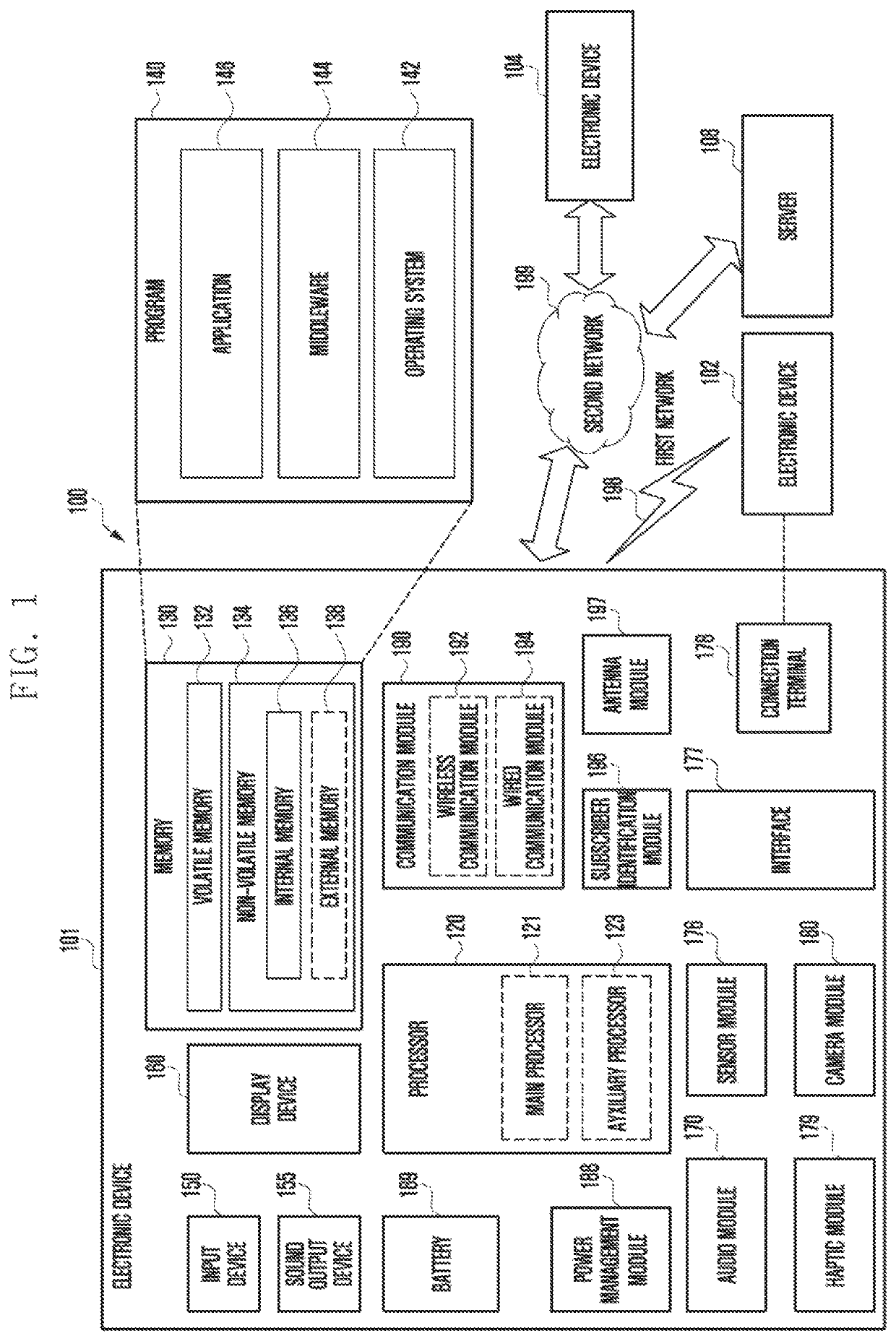
[0033]The following description with reference to the accompanying drawings is provided to assist in a comprehensive understanding of the various embodiments of the disclosure as defined by the claims and their equivalents. It includes various specific details to assist in that understanding but these are to be regarded as merely exemplary. Accordingly, those of ordinary skill in the art will recognize that various changes and modifications of the various embodiments described herein can be made without departing from the scope and spirit of the disclosure. In addition, descriptions of well-known functions and constructions may be omitted for clarity and conciseness.

[0034]The terms and words used in the following description and claims are not limited to the bibliographical meanings, but, are merely used by the inventor to enable a clear and consistent understanding of the disclosure. Accordingly, it should be apparent to those skilled in the art that the following description of va...


PUM


Abstract

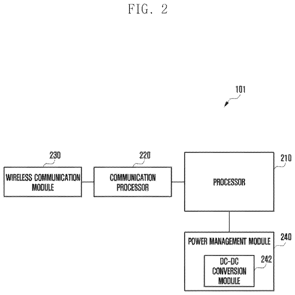
An apparatus and a method for controlling a voltage conversion mode in an electronic device are provided. The electronic device includes a power management module, a communication processor, and at least one processor operably connected to the communication processor, wherein the at least one processor identifies a modulation order used for communication with an external device, in a case that communication with the external device is performed using a wireless resource, and configures, based on the modulation order, a voltage conversion mode of the power management module that supplies power to the communication processor to a pulse frequency modulation (PFM) mode or a pulse width modulation (PWM) mode.

Description

CROSS-REFERENCE TO RELATED APPLICATION(S)[0001]This application is based on and claims priority under 35 U.S.C. § 119(a) of a Korean patent application number 10-2019-0126384, filed on Oct. 11, 2019, in the Korean Intellectual Property Office, the disclosure of which is incorporated by reference herein in its entirety.BACKGROUND1. Field[0002]The disclosure relates to an apparatus and a method for controlling a voltage conversion mode in an electronic device.2. Description of Related Art[0003]An electronic device may include a voltage converter for stably supplying a voltage of a predetermined level to an internal circuit. A voltage converter may include a direct-current / direct-current (DC-DC) converter which converts, to a direct current voltage of a predetermined level (for example: 5 V), a direct current voltage supplied from a battery of an external device or an external power source and outputs the converted direct current voltage. For example, a DC-DC converter may support a bu...

Claims


Application Information

Patent Timeline
Patent Type & Authority Patents(United States)
IPC IPC(8): H02M1/14H02M3/158H04L1/00H04L27/12
CPCH02M1/143H02M3/158H04L1/0003H04L27/12H02M3/00H04L1/0036H02M1/44H04L27/0008H02M3/10H02M3/156G06F1/26
Inventor PARK, SUNGCHULSON, DONGILYOON, SUHAJUNG, EUICHANG
Owner SAMSUNG ELECTRONICS CO LTD
Learn More