Supercharge Your Innovation With Domain-Expert AI Agents!

Vent assembly for a ventilation system

a technology for ventilation systems and vent assemblies, applied in space heating and ventilation details, lighting and heating apparatuses, heating types, etc., can solve the problems of increased risk of breathing problems, poor design, and living in damp or moldy environments, and achieve the effect of reducing the accumulation of dus

Active Publication Date: 2021-11-23
AFKHAMPOUR KHOSROW ANTHONY
View PDF9 Cites 0 Cited by
  • Summary
  • Abstract
  • Description
  • Claims
  • Application Information

AI Technical Summary

Benefits of technology

The present invention relates to an air conditioning system that prevents the return of exhaust air, is economical to manufacture, prevents the intake of polluted air, avoids the mixing of air between residential units, and reduces the accumulation of dust in duct or pipes. These technical effects are achieved through the use of an assembly or system that addresses each of these issues simultaneously.

Problems solved by technology

Living in damp or moldy environments has been linked to increased risks of breathing problems, such as asthma.
There are problems associated with central exhaust systems that can be linked to a) poor design (inadequate fan power), b) poor installation (improper sealing of connection between horizontal pipe and stack), c) mode of operations (not adjusting fan power for variation of temperatures in hot and cold seasons), and d) lack of proper maintenance (loss of suction due to corrosion which is caused by condensation of moist air in the connecting pipes to the main shaft) or combinations of these issues.
Loss of vacuum in the main shaft due to the abovementioned problems results in the return of mixed exhaust air back into the bathrooms and other living spaces, which can be a serious health hazard.
The problem is exacerbated by the opening and closing the bathroom door (or other spaces with vent) which acts like an air pump (blower).
Furthermore, in the event of a fire in one of the units, the smoke can find its way into other units, via the main stack and connecting pipes, and create a health hazard situation.
Living in damp or moldy environments has been linked to increased risks of breathing problems, such as asthma.

Method used


Image

  • Vent assembly for a ventilation system
  • Vent assembly for a ventilation system
  • Vent assembly for a ventilation system

Examples


Embodiment Construction

[0032]Subject matter will now be described more fully hereinafter with reference to the accompanying drawings, which form a part hereof, and which show, by way of illustration, specific exemplary embodiments. Subject matter may, however, be embodied in a variety of different forms and, therefore, covered or claimed subject matter is intended to be construed as not being limited to any exemplary embodiments set forth herein; exemplary embodiments are provided merely to be illustrative. Likewise, the reasonably broad scope for claimed or covered subject matter is intended. Among other things, for example, the subject matter may be embodied as methods, devices, components, or systems. The following detailed description is, therefore, not intended to be taken in a limiting sense.

[0033]The word “exemplary” is used herein to mean “serving as an example, instance, or illustration.” Any embodiment described herein as “exemplary” is not necessarily to be construed as preferred or advantageou...


PUM


Abstract

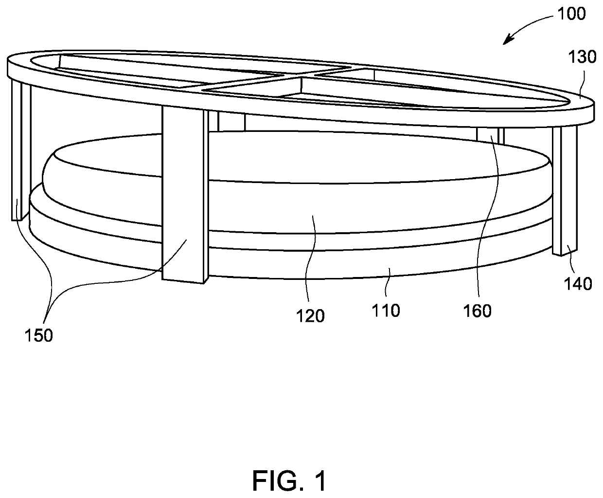
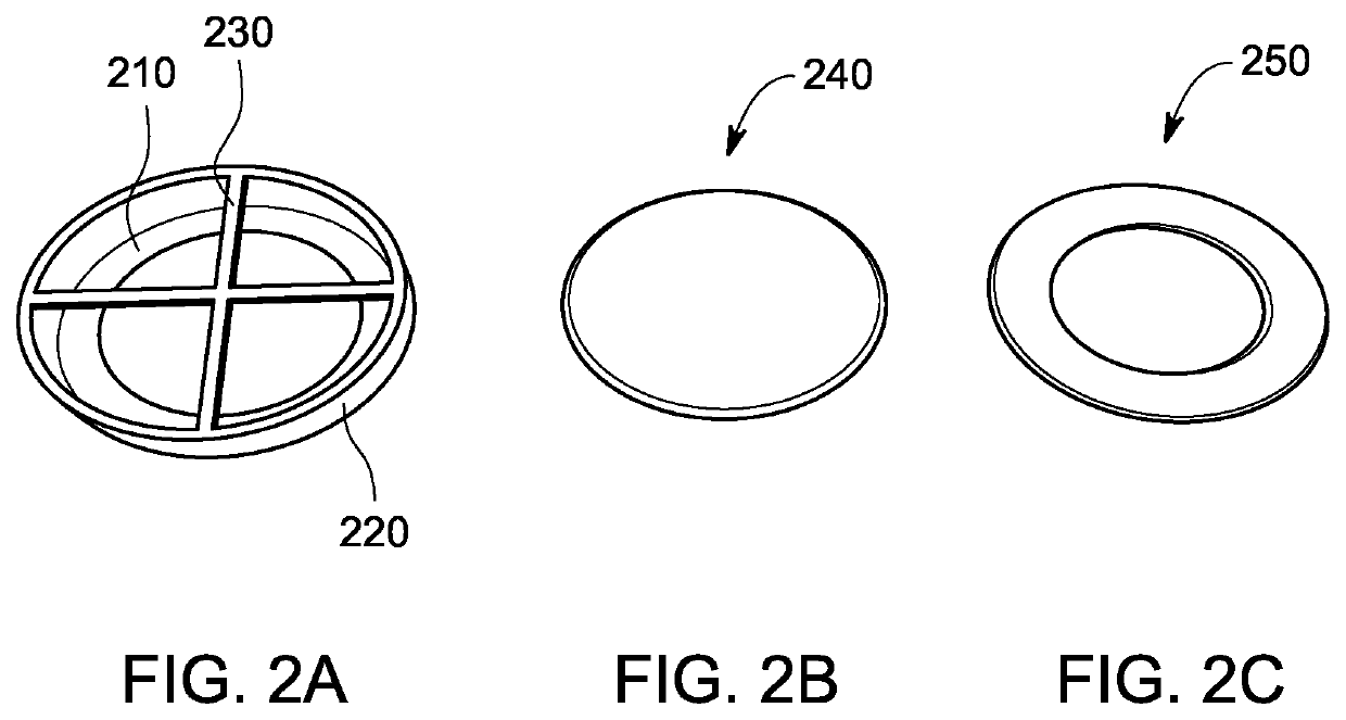
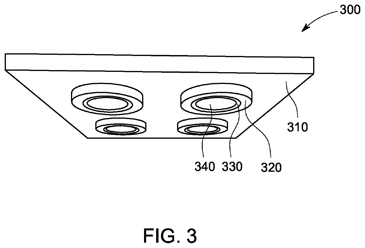
Disclosed is an air vent assembly for ventilation systems. The disclosed vent assembly regulates the flow of exhaust air sucked by an exhaust fan of the ventilation system. The vent assembly includes a seat, the seat having a passage for air. The seat can be configured in a base that can be installed over a vent or a grille on the vent. The assembly further includes a lid placed on the seat, such as to block the passage of the seat. A cage surrounding the lid, wherein the cage limits the lateral movement of the lid and provides a guided upper movement of the lid. The cage is of a slanted configuration. The lid can be held against the top of the cage in an inclined position, wherein the angle of inclination can be proportional to the slant of the cage.

Description

FIELD OF INVENTION[0001]The present invention relates to the field of exhaust ventilation systems, and more particularly the present invention relates to an air vent assembly for regulating the flow of exhaust air in a ventilation system and preventing the accumulation of dust and pollutants in the ducts of an air-conditioning system.BACKGROUND[0002]Nearly all buildings require mechanical ventilation systems to exhaust pollutants generated inside the building, such as moisture and vapors from bathrooms, laundry rooms, cooking, and chemicals from building materials and cleaners. Buildings that are ventilated well are less likely to experience unhealthy odor or moisture / mold issues. Living in damp or moldy environments has been linked to increased risks of breathing problems, such as asthma.[0003]Central exhaust ventilation systems are the most common type of ventilation systems used in mid to high-rise multi-family buildings constructed after the 1960s. The roof-top electrical fans w...

Claims


Application Information

Patent Timeline
IPC IPC(8): F24F13/10
CPCF24F13/10F24F13/14F24F13/1426F24F13/20
Inventor AFKHAMPOUR, KHOSROW ANTHONY
Owner AFKHAMPOUR KHOSROW ANTHONY
Features
  • R&D
  • Intellectual Property
  • Life Sciences
  • Materials
  • Tech Scout
  • Unparalleled Data Quality
  • Higher Quality Content
  • 60% Fewer Hallucinations
Learn More