
Extruder

a technology of extruder and extruder plate, which is applied in the field of extruder, can solve the problems of large, large, expensive, and relatively energy-inefficient, and achieve the effect of reducing the potential for strain orientation lines to be formed within the molded component, reducing the potential for strain orientation lines, and eliminating the effect of strain orientation

Active Publication Date: 2021-12-14
OMACHRON INTPROP
View PDF26 Cites 0 Cited by
  • Summary
  • Abstract
  • Description
  • Claims
  • Application Information

AI Technical Summary

Benefits of technology

The patent is about a method for reducing heat damage to plastic materials during manufacturing. This is achieved by using an extruder that minimizes heat transfer through the conveyed material. The extruder has a high heat transfer rate through its barrel wall, which allows for more heat to be transferred to the material per unit time. This decreases the amount of shear heating required to melt the plastic material. Additionally, the patent discusses a method to produce molded components without strain orientation lines, which typically require post molding treatment. This method fills the mold cavity at a low pressure and material flow rate, reducing the potential for strain orientation lines.

Problems solved by technology

For example, excessive shearing of the plastic material may lead to a physical and / or chemical degradation of the polymer molecules within the plastic material.
In typical extrusion or injection molding operations, large plastic components are produced using machines capable of relatively high injection pressures (e.g., 5,000 to 20,000 psi), which are often large, expensive, and may be characterized as being relatively energy inefficient.
As the plastic material exiting the extruder is in a flowable state due to its elevated temperature, if the flowable material is allowed to cool, it will begin to solidify, which may not be desirable until the mold has been completely filled and pressurized by the pressurization member.
A possible downside of such a process is the potential for the introduction of strain orientation lines within the plastic component.

Method used


Image

  • Extruder
  • Extruder
  • Extruder

Examples


Embodiment Construction

[0145]Various apparatuses, methods and compositions are described below to provide an example of an embodiment of each claimed invention. No embodiment described below limits any claimed invention and any claimed invention may cover apparatuses and methods that differ from those described below. The claimed inventions are not limited to apparatuses, methods and compositions having all of the features of any one apparatus, method or composition described below or to features common to multiple or all of the apparatuses, methods or compositions described below. It is possible that an apparatus, method or composition described below is not an embodiment of any claimed invention. Any invention disclosed in an apparatus, method or composition described below that is not claimed in this document may be the subject matter of another protective instrument, for example, a continuing patent application, and the applicant(s), inventor(s) and / or owner(s) do not intend to abandon, disclaim, or d...


PUM

PropertyMeasurementUnit
pressureaaaaaaaaaa
diameteraaaaaaaaaa
wall thicknessaaaaaaaaaa

Abstract

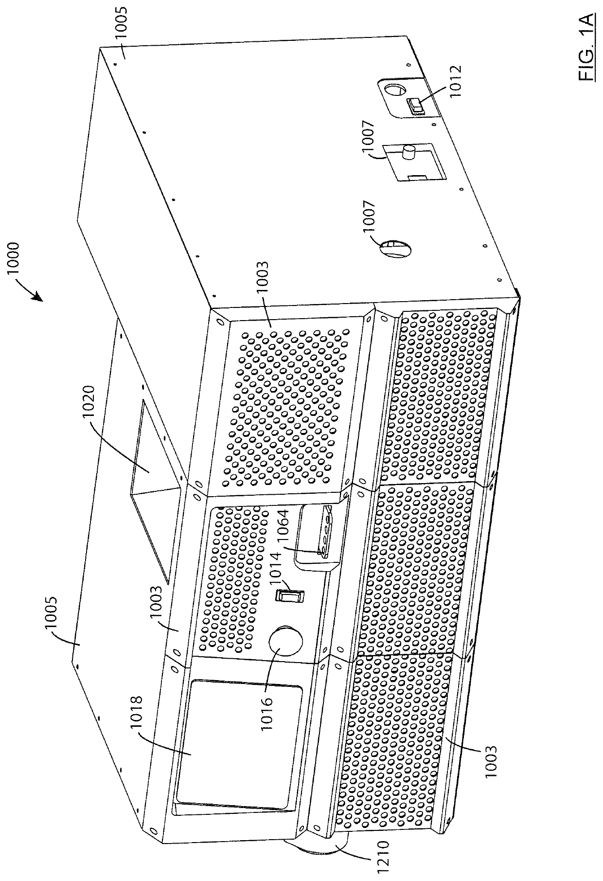
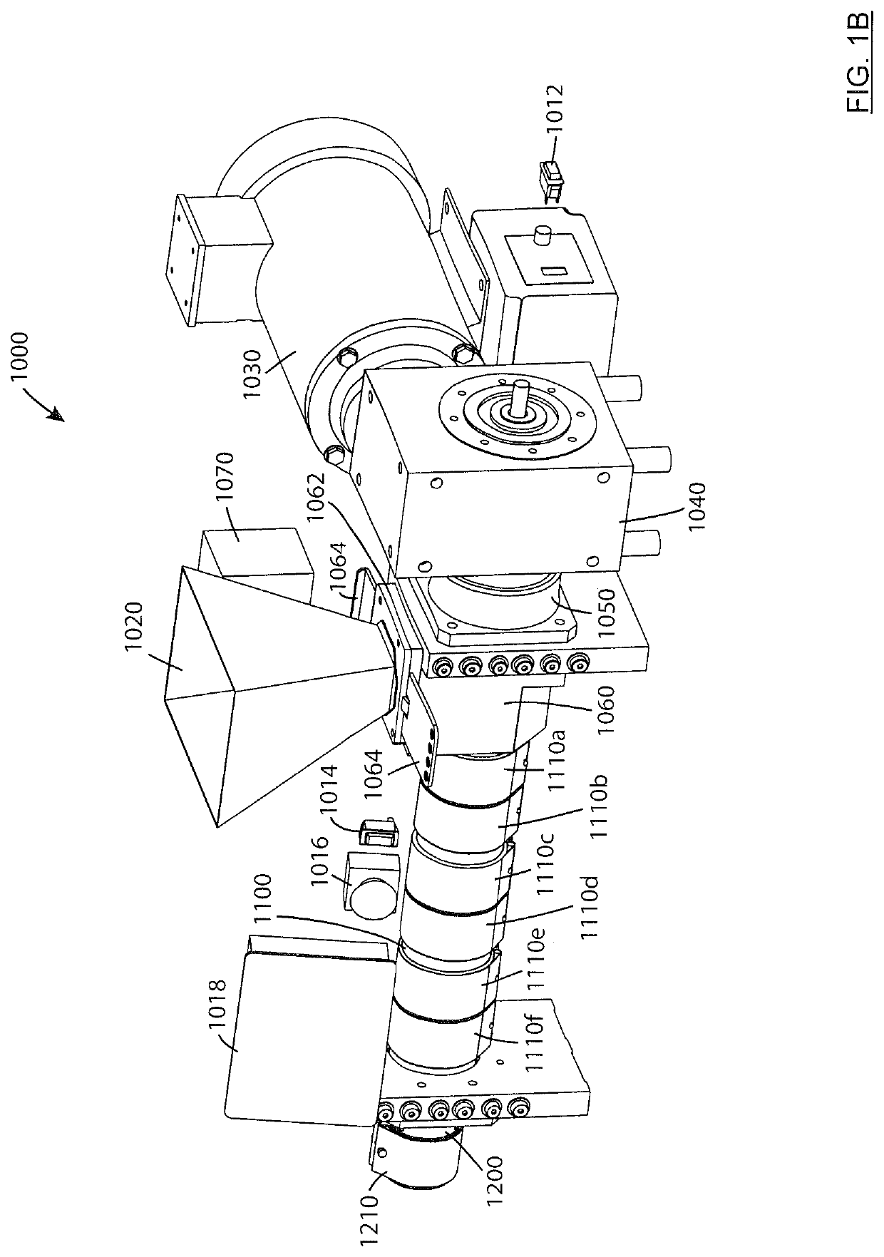
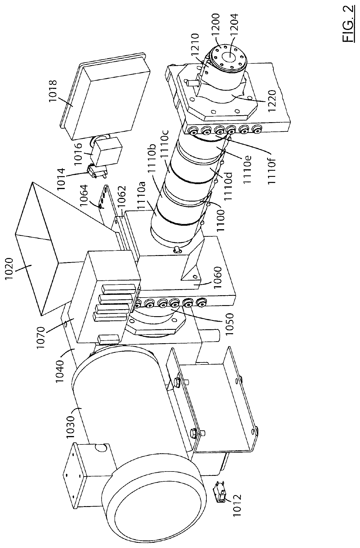
An extruder has a barrel extending from a feed inlet end to an extruder outlet end. The barrel has an inner surface, an outer surface, and a wall thickness between the inner and outer surfaces. The extruder also has at least one heating member positioned provided on the barrel; a screw drive motor drivingly connected to a rotatably mounted screw positioned within the barrel, whereby the screw is rotatable at various revolutions per minute (RPM); and a controller is operably connected to the screw drive motor to adjust the RPM of the screw based upon a temperature of material passing through and / or being extruded from the barrel. Methods for operating an extruder filling a mold are also provided.

Description

FIELD[0001]This disclosure relates generally to extruders, and more specifically to extruders for extruding a plastic or thermoplastic material. This disclosure also relates to methods using one or more extruders to produce an extruded or molded plastic part.INTRODUCTION[0002]Extruders are typically used to heat and melt a solid input material (e.g. a plastic, or thermoplastic material) and extrude the material in a flowable, or melted state. The extruded, or output, material may be directed through a form or die while it cools and solidifies to form an elongate plastic component having a cross-sectional profile defined by the form or die. Alternatively, the output material may be directed into a mold where it is then cooled and solidifies to form a molded component having a shape defined by the mold.[0003]One source of the heat provided to raise the temperature of the conveyed plastic material as it passes through the extrusion or injection barrel is mechanical shear heating. In sh...

Claims


Application Information

Patent Timeline
Patent Type & Authority Patents(United States)
IPC IPC(8): B29C48/92B29C48/395B29C48/68B29C48/86B29C48/25B29C45/57B29C45/50B29C48/80B29C45/54B29C49/78B29C45/26B29C48/64B29C45/18B29C45/47B29C45/58B29C45/73B29C48/53B29C48/03B29C48/505B29C48/02B29C48/60B29L23/00
CPCB29C48/92B29C45/18B29C45/2669B29C45/47B29C45/5092B29C45/54B29C45/57B29C45/58B29C45/73B29C48/2526B29C48/397B29C48/64B29C48/681B29C48/6803B29C48/832B29C48/865B29C49/78B29C48/02B29C48/03B29C48/509B29C48/53B29C48/60B29C48/6801B29C2948/924B29C2948/9238B29C2948/9259B29C2948/92209B29C2948/92447B29C2948/92885B29C2948/92952B29K2995/0094B29L2023/22B29K2105/04
Inventor CONRAD, WAYNE ERNEST
Owner OMACHRON INTPROP
Learn More