
Front axle assembly and vehicle with the same

a technology for front axles and vehicles, applied in the direction of vehicle components, fastening means, rod connections, etc., can solve the problems of u-joints, seals, and damage to the u-joints of the front axle, and the integration of the front axle assembly has not been substantially improved

Active Publication Date: 2021-12-21
SHANGHAI LINGHUO TRADING CO LTD
View PDF5 Cites 5 Cited by
  • Summary
  • Abstract
  • Description
  • Claims
  • Application Information

AI Technical Summary

Benefits of technology

The present disclosure provides a front axle assembly that can conveniently and independently adjust vehicle's caster angles on both sides and the pinion to driveshaft angle simultaneously while ensuring the support strength. The original position and angle of the mounting points of all components on the axle tube is still intact, and the variables that affect the chassis wheelbase, directional accuracy, and suspension height will not be introduced. The inner-C-forging can be rotated around its own axis to an appropriate angle and then be fixed to the axle tube, through which the caster angle can be adjusted by changing the installation angle of the inner-C-forging. The mounting points of all components can be arranged on the complete axle tube, which ensures the vehicle's caster angles on both sides and the pinion to driveshaft angle simultaneously can be conveniently and independently adjusted while ensuring the support strength.

Problems solved by technology

Since the launch of the first off-road vehicle model, the appearance, interior trim, four-wheel drive technology, and power system of the off-road vehicle have made great progress, however, as the core of the chassis, the integral front axle assembly has not been substantially improved.
However, the lift of the vehicle chassis also brings the following problems that obviously affect the vehicle handling experience, moreover, seriously threaten the safety of the people in the vehicle.
1. With the vehicle chassis lifted, the pinion to driveshaft angle has increased, causing the u-joint of the driveshaft to vibrate, thereby easily damaging the u-joints, seals, etc., and greatly increasing the probability of abnormal damage to the driveshaft and transfer case.
At the same time, obvious chassis vibration is generated due to the distortion of these components during the running of the vehicle.
Consequently, when the vehicle is driving in a straight line, the front wheels will vibrate, the steering wheel will swing indeterminately, and the steering will be touchy at high speed and wheel return-to-center will be diminished when coming out of a turn, which makes the driver lose the road feeling and have no confidence in the vehicle handling even when driving on conventional roads.
3. The increase in tire diameter, the wear of tires, the left-right imbalance of the suspension system, and the combination of other factors cause the vehicle fail to run straight and even sway to left and right.
Although the problem of not being able to run straight can be fundamentally solved by independently and properly adjusting the caster angle on one side, however, both inner-C-forgings on all the current integral front axle assemblies have been welded to the axle tube as a factory setting, thus, the caster angle cannot be independently adjusted.
However, not only this approach cannot fundamentally solve the problem of not being able to run straight, but also can make the vehicle produce distortion feeling when turning because the wheelbases on both sides are different from each other and no longer form a regular rectangle as the vehicle leaves the factory.
In the course of running, the tires on both sides will do serpentine motion because of the wheelbases inconsistency, as a result, the direct feeling of driver is that the chassis is loose and unstable.
The fundamental reason why the above problems can not be solved is because of the common structural design of all the integral front axle assemblies in the current market: the caster angles on both sides and the pinion to driveshaft angle can not be independently adjusted, thus, consumers can only bear various vehicle handling problems and major potential safety hazards caused by this design.
What global automakers and modification shops can do is to spend a lot of labor and time to continuously fine-tune the vehicles with underwhelming result, which leads to low customer satisfaction.

Method used


Image

  • Front axle assembly and vehicle with the same
  • Front axle assembly and vehicle with the same
  • Front axle assembly and vehicle with the same

Examples


Embodiment Construction

[0042]Embodiments of the present disclosure will now be described more apparently and completely with reference to the embodiments. Obviously, the illustrated embodiments are only a part but not all of the embodiments of the present disclosure. All the other embodiments which could be obtained without creativity by one of ordinary skill in the art according to the illustrated embodiments would be claimed within the scope of the present disclosure.

[0043]The present disclosure provides a front axle assembly and a vehicle with the same. The front axle assembly can conveniently adjust the caster angle of a kingpin knuckle of the vehicle while ensuring the support strength.

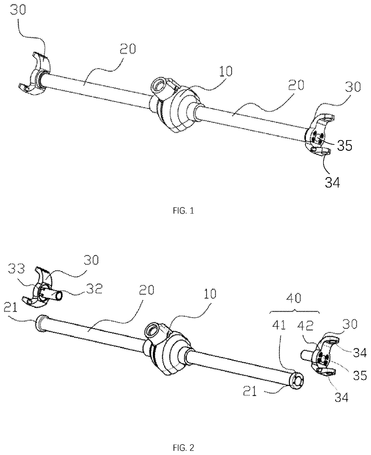
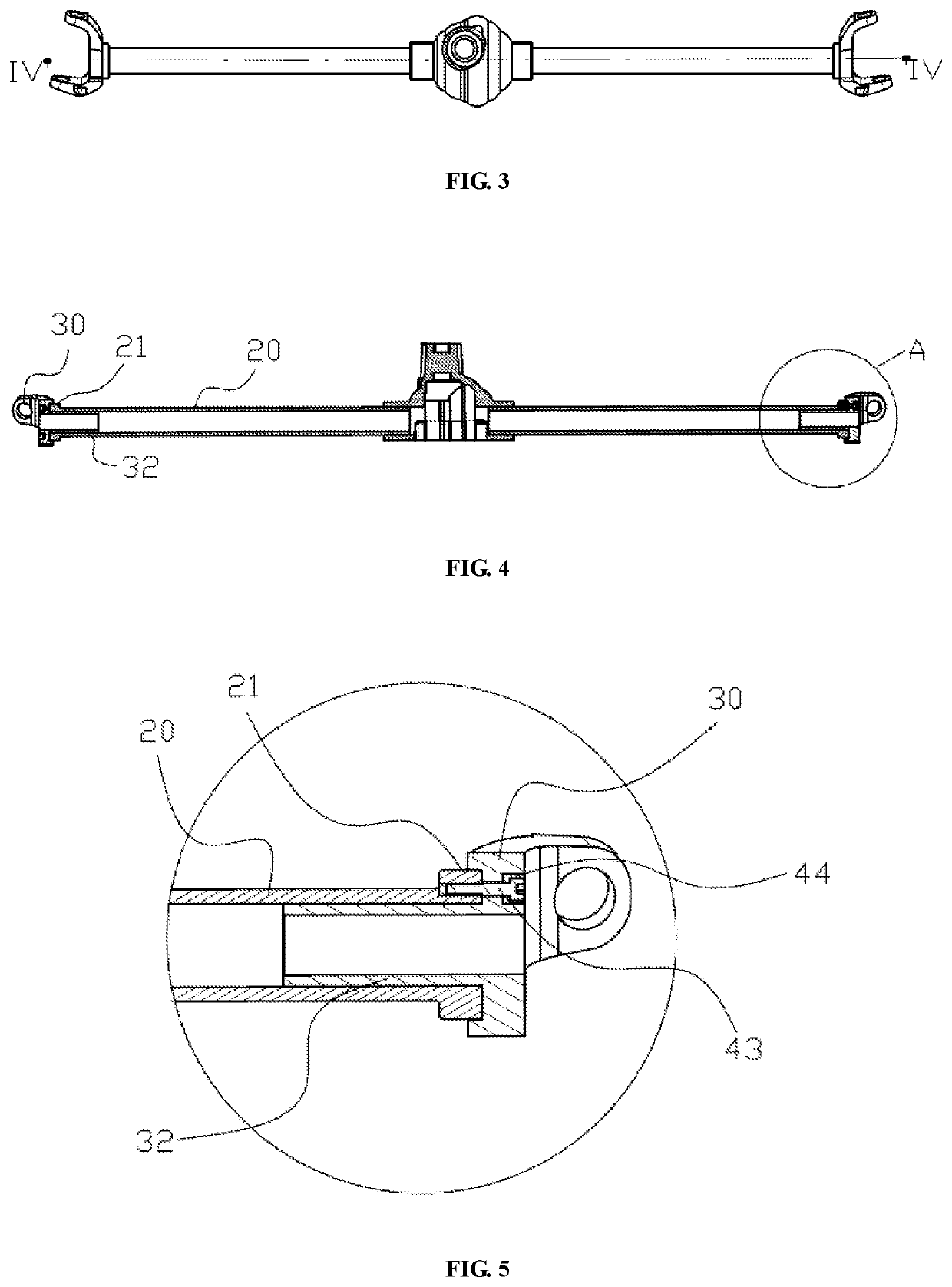
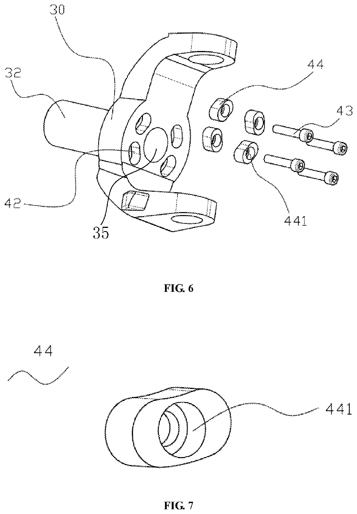
[0044]FIG. 1 is a schematic, isometric view of a front axle assembly according to a first embodiment of the present disclosure. FIG. 2 is a schematic, exploded view of the front axle assembly of FIG. 1. FIG. 3 is a schematic, front view of the front axle assembly of FIG. 1. FIG. 4 is a schematic, cross-sectional view t...


PUM


Abstract

The present disclosure provides an integral front axle assembly which includes an axle housing configured for connecting with a driveshaft; two axle tubes respectively connected with two opposite sides of the axle housing; two inner-C-forgings disposed at ends of the axle tubes and each being configured for connecting with a kingpin knuckle; and at least one connection structure, for detachably fixing at least one of the inner-C-forgings to a corresponding axle tube. The inner-C-forging has different mounting positions on the axle tube, correspondingly, the caster to pinion angle is different at inner-C-forging's different mounting positions. The caster angles on both sides and the pinion to driveshaft angle can be conveniently and independently adjusted while ensuring the support strength.

Description

CROSS REFERENCE TO RELATED APPLICATION[0001]The patent application claims the priority of Chinese patent application number 202110682630.1, filed on Jun. 18, 2021, submitted by Shanghai Yinshun Trading Co., Ltd., and entitled “INTEGRAL FRONT AXLE AND VEHICLE WITH THE SAME”, and Chinese patent application number 202121371525.8, filed on Jun. 18, 2021, submitted by Shanghai Yinshun Trading Co., Ltd., and entitled “INTEGRAL FRONT AXLE AND VEHICLE WITH THE SAME”. The entire disclosure of the above-identified application is incorporated herein by reference.FIELD OF THE INVENTION[0002]The present disclosure relates to automobile structures, and in particular to a front axle assembly and a vehicle with the same.BACKGROUND OF THE INVENTION[0003]Since the launch of the first off-road vehicle model, the appearance, interior trim, four-wheel drive technology, and power system of the off-road vehicle have made great progress, however, as the core of the chassis, the integral front axle assembly...

Claims


Application Information

Patent Timeline
Patent Type & Authority Patents(United States)
IPC IPC(8): B60B35/16B62D7/18B60B35/12F16B7/04
CPCB60B35/16B60B35/122B62D7/18F16B7/0406B62D17/00B60B35/003B60B35/009
Inventor DU, DEHUIFU, JIA
Owner SHANGHAI LINGHUO TRADING CO LTD
Learn More