
Shape sensing for orthopedic navigation

a technology of shape sensing and orthopedics, applied in the field of shape sensing, can solve the problems of not only requiring line-of-sight, but also only being accurate within a defined volume, and unable to provide valid measurement of tracking attachments that are not visible by the camera, so as to accelerate the registration in orthopedics

Active Publication Date: 2022-01-11
KONINKLJIJKE PHILIPS NV
View PDF13 Cites 2 Cited by
  • Summary
  • Abstract
  • Description
  • Claims
  • Application Information

AI Technical Summary

Benefits of technology

[0010]A shape sensing system in accordance with the present invention may further include optical shape sensing fiber that can be used to accelerate registration in orthopedics and generally. The optical shape sensing fiber can be integrated in a registration device to provide a convenient way of sampling points on or a shape of, a bone or of another object and avoid point-by-point acquisition of registration landmarks. The rapid registration can be implemented using (1) discrete landmarks on the bone or other object, or (2) exact shape matching to the actual shape of part (or all) of the bone or other object, as measured by the optical shape sensing fiber. For each rapid registration method, exemplary corresponding hardware components of a registration device are described herein. In particular, wearable shape sensed devices such as registration gloves and rings can be used for fast acquisition of the discrete landmarks. Devices which include a superelastic patch or a shape memory tube may also be used advantageously to capture the shape of a (partial) bone or other object.
[0011]A shape sensing system in accordance with the present invention may also include a medical device such as a registration tool, rapid registration device or similar medical instrument and a method of use of such a device, the device having a pointer tip capable of being passed through a minimally invasive incision to reach areas not in a direct line-of-sight from the incision. A one degree-of-freedom (DoF) steerable tip with a ‘manual’ six DoF directioning available at a handle or other fixture of the device provides many different possible tip positions and orientations. Registration points can be acquired flexibly with one DoF at an end or tip of a device which also has optical shape sensing deployed or embedded along the device's length so that device shape, position, and, orientation along the fiber are known and patient anatomy can be registered to a pre-operative plan. Hence, the optical shape sensing fiber can be used to enable registration along curved pathways inside a body and at a point varied flexibly at a tip of the device.

Problems solved by technology

Any tracking attachments that are not visible by the cameras cannot provide a valid measurement.
It can be difficult to maintain an unobstructed path during all parts of the procedure, especially when, e.g., a bone is manipulated to test the dynamic biomechanics.
These CAS systems not only require line-of-sight, but are also only accurate within a defined volume.
This volume is with respect to the camera position and can be difficult to maintain throughout the procedure, especially during manipulation of the joint.
Such large attachments limit the physical workspace available to the clinicians and risk collisions intra-operatively.
These screw pins can lead to adverse effects such as stress fractures (especially in the case of two pins used close together), infection, nerve injury, pin loosening (leading to additional pins or inaccuracies in the measurement), etc.
Similar to line-of-sight tracking, it can be difficult to maintain an optimal clinical workflow while also satisfying the requirements of the EM system.
Further, metal in the EM field can generate interference and degrade the accuracy of the measurement.

Method used


Image

  • Shape sensing for orthopedic navigation
  • Shape sensing for orthopedic navigation
  • Shape sensing for orthopedic navigation

Examples


Embodiment Construction

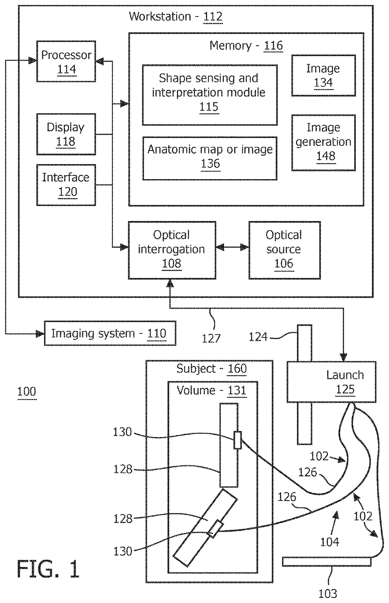
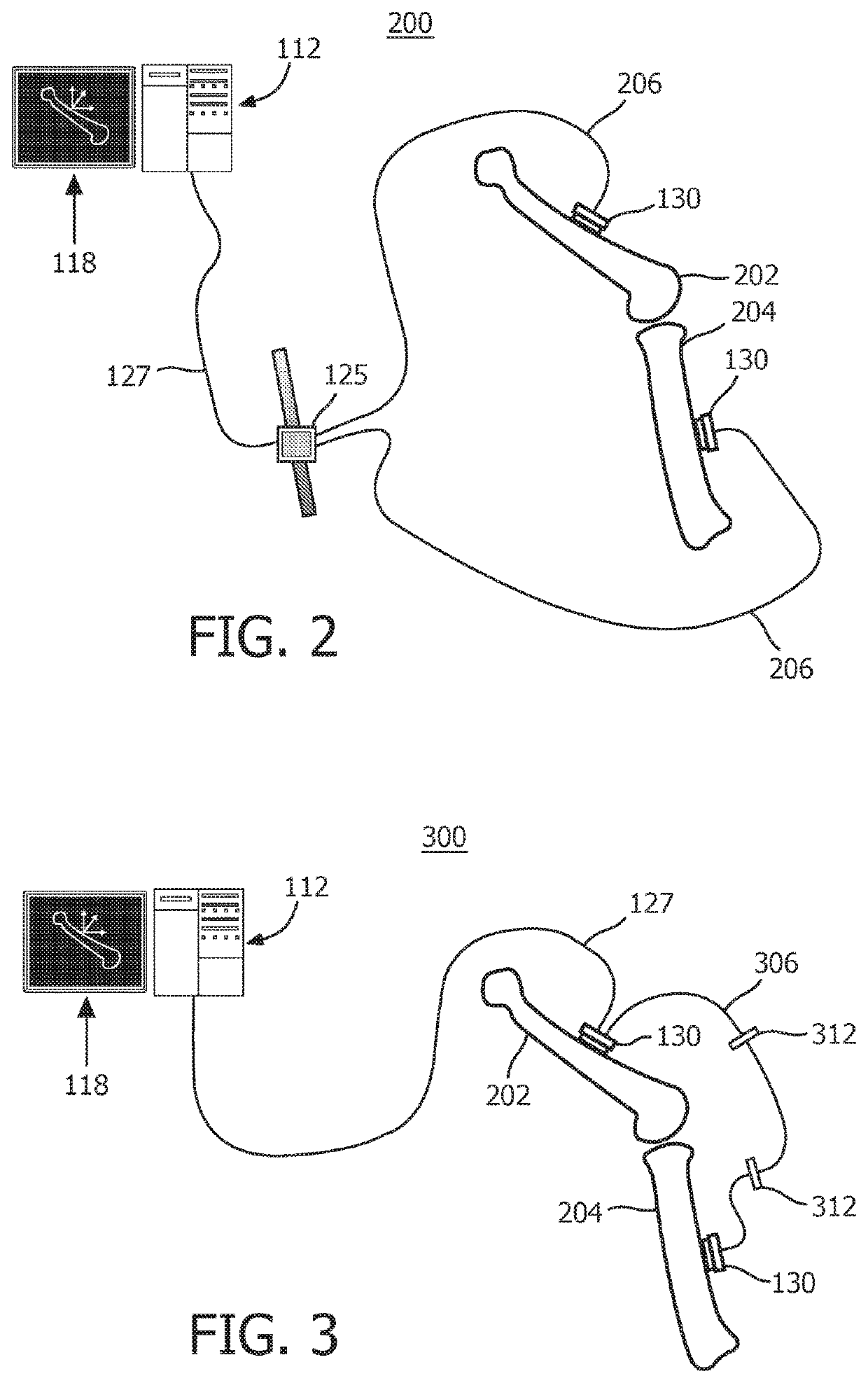
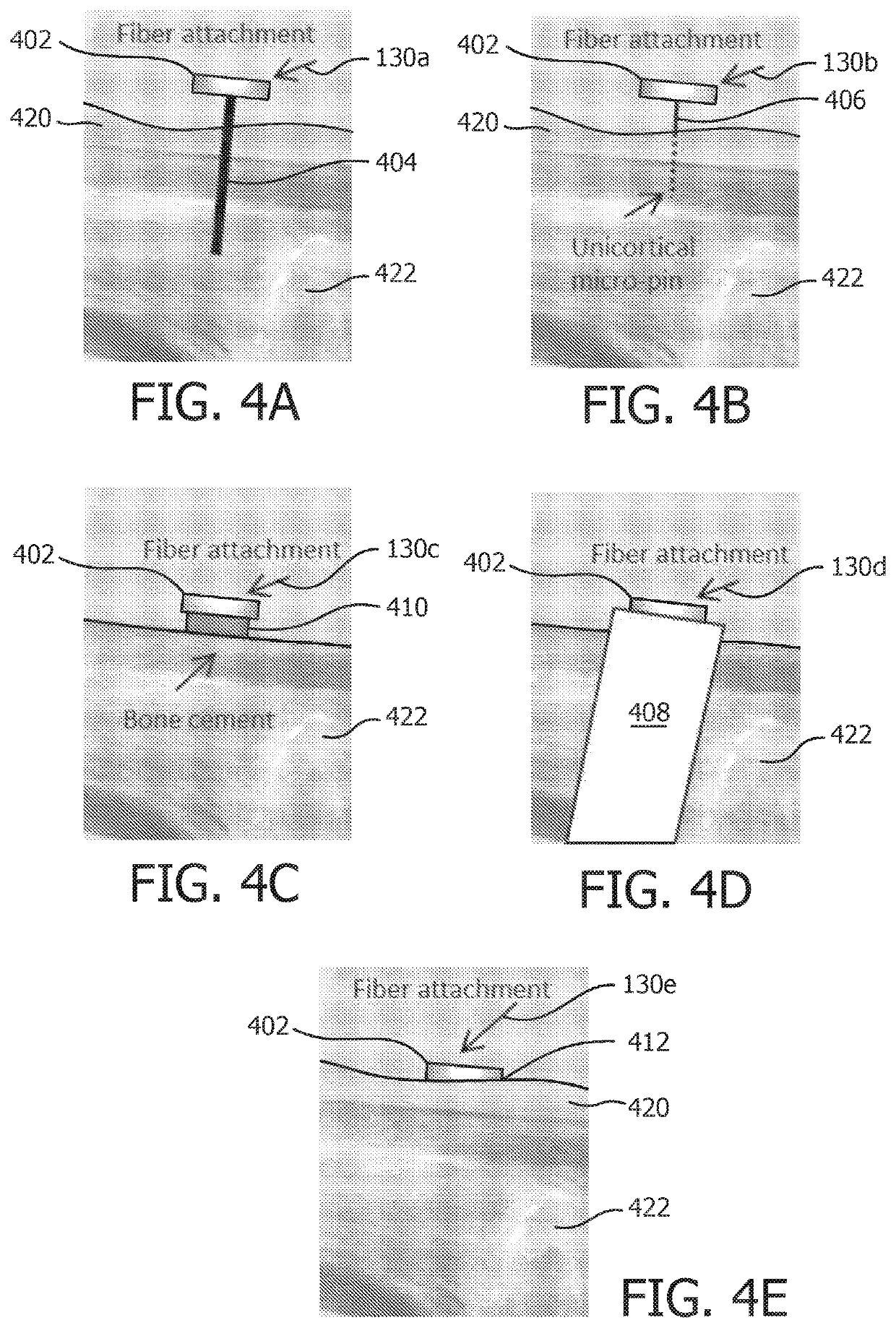
[0043]In accordance with the present principles, systems and methods are provided for shape sensing that can be used for displaying relative position of instruments and implants overlaid on an anatomical map during a surgical procedure. In one embodiment, the shape sensing employs shape sensing optical fiber attached to the patient, and the shape sensing measurement can be registered to the anatomical map. The position of the shape sensing markers with respect to an anatomical map can be displayed for a user. In addition, shape sensing optical fiber may be attached to orthopedic or other instruments such as drills and cutting rigs to track their positions. Optical shape sensing uses light along a multicore optical fiber to reconstruct the shape along that fiber. The principle involved makes use of distributed strain measurement in the optical fiber using characteristic Rayleigh backscatter or controlled grating patterns. The shape along the optical fiber begins at a specific point a...


PUM


Abstract

An optical shape sensing system includes an attachment device (130) coupled at an anatomical position relative to a bone. An optical shape sensing fiber (102) is coupled to the attachment device and configured to identify a position and orientation of the attachment device. An optical shape sensing module (115) is configured to receive feedback from the optical shape sensing fiber and register the position and orientation of the attachment device relative to an anatomical map.

Description

CROSS-REFERENCE TO PRIOR APPLICATIONS[0001]This application is the U.S. National Phase application under 35 U.S.C. §371 of International Application Serial No. PCT / IB2015 / 056595, filed on Aug. 31, 2015, which claims the benefit of U.S. application Ser. No. 62 / 047,338, filed on Sep.8, 2014. These applications are hereby incorporated by reference herein.BACKGROUNDTechnical Field[0002]This disclosure relates to systems and methods for use in computer assisted surgery, and more specifically, to the use of shape sensing for tracking anatomical positions and surgical tools during an orthopedic procedure.Description of the Related Art[0003]Computer assisted surgery (CAS) systems are used for preoperative planning and intra-operative surgical navigation. In this context, preoperative planning refers to any computer assisted determination of surgical steps, such as cutting, incisions, targeting, etc. Planning can occur before or during a procedure. The preoperative planning often uses 2D or ...

Claims


Application Information

Patent Timeline
Patent Type & Authority Patents(United States)
IPC IPC(8): A61B34/20A61B34/10A61B90/00A61F2/46A61B34/00A61B17/00
CPCA61B34/20A61B34/10A61B90/37A61F2/4657A61B2017/00438A61B2034/108A61B2034/2055A61B2034/2061A61B2034/2068A61B2034/741A61B2090/067A61B2090/365A61B2090/374A61B2090/376A61B2090/378A61B2090/3762A61F2002/4663
Inventor HE, XINGCHIPOPOVIC, ALEKSANDRAFLEXMAN, MOLLY LARATHIENPHRAPA, PAULNOONAN, DAVID PAULKROON, RONREINSTEIN, ARYEH LEIB
Owner KONINKLJIJKE PHILIPS NV
Learn More