
Long thin glass body

a thin glass and body technology, applied in the field of thin glass elongated body, can solve the problems of air trapped between thin glass and the film to generate air bubbles, and thin glass being liable to be broken, so as to achieve stable manufacturing and less trouble

Active Publication Date: 2022-01-11
NITTO DENKO CORP
View PDF29 Cites 0 Cited by
  • Summary
  • Abstract
  • Description
  • Claims
  • Application Information

AI Technical Summary

Benefits of technology

The present invention provides a way to make thin glass with small air bubbles between the glass and the resin film. This is done by adding cutting lines and holes in the resin film that go through it. This process helps to make stable thin glass elongated bodies without breaking them and trapping air between them.

Problems solved by technology

The thin glass involves problems in that the thin glass is liable to be broken in its processing or treatment owing to its extreme fragility, a device is fouled with glass pieces resulting from the breakage, excessive caution is required for restoration of the fouled device, and the like.
However, when a film, such as the protective film, is bonded onto the thin glass, there is a problem in that air is trapped between the thin glass and the film to generate air bubbles.
In the case where the thin glass having the film is taken up with the air bubbles generated, the thin glass is liable to be broken due to the air bubbles.
Further, in the case where the thin glass having the film with the air bubbles generated is subjected to a roll-to-roll process into which laminate roll, a nip roll, or the like is incorporated, the air bubbles accumulate at an inlet of the roll and increase in size while the thin glass having the film continuously passes through the roll, with the result that troubles are liable to occur during processing and conveyance.
Further, in the thin glass having the film having a difference in surface level, air is liable to be trapped between the thin glass and the film during bonding, and thus the above-mentioned problem becomes more conspicuous.
Various problems are caused in the thin glass having the film with the air bubbles generated, and hence, in the case where air is trapped between the thin glass and the film during bonding of the film, an attempt is generally made to perform peeling and rebonding (rework) of the film.
However, the thin glass serving as an adherend is liable to be broken during peeling of the film, and it is also difficult to rework the film.

Method used


Image

  • Long thin glass body
  • Long thin glass body
  • Long thin glass body

Examples


example 1

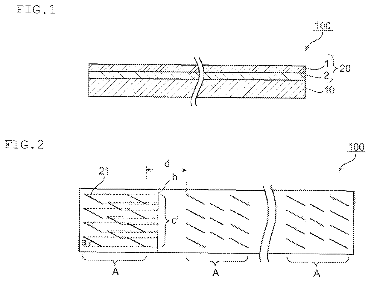
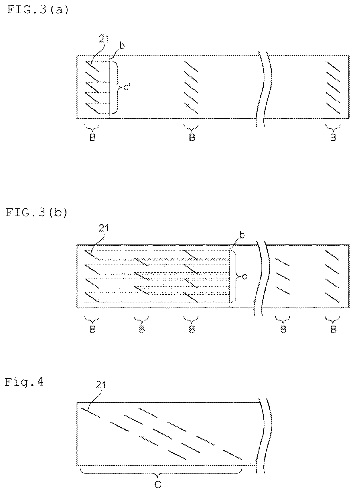
[0065]A resin film (PET film, total thickness: 25 μm) including a pressure-sensitive adhesive layer was laminated on the entire surface on one side of a thin glass (thickness: 50 μm) having a length of 20 m and a width of 300 mm to subject the thin glass and the resin film to preliminary bonding. Then, cutting lines were formed in the resin film as illustrated in FIG. 2. The length of each cutting line was set to 40 mm and the inclined angle a thereof was set to 45°. Further, a group A having 11 cutting lines (4 cutting lines / 3 cutting lines / 4 cutting lines in 3 rows) was formed in a region having a width of 300 mm and a length of 500 mm. The eight groups A were formed at an interval of 2 m. Further, in each of the groups A, a set of projection lines obtained by projecting the cutting lines in each group onto one imaginary line b parallel to the width direction of the resin film formed one continuous line c′. In this case, the length of the continuous line c′ was set to 90% with res...


PUM

PropertyMeasurementUnit
angleaaaaaaaaaa
thicknessaaaaaaaaaa
lengthaaaaaaaaaa

Abstract

There is provided a thin glass elongated body having a small amount of air bubbles between a thin glass and a resin film. A thin glass elongated body of the present invention includes: a thin glass having an elongated shape; and a resin film bonded onto at least part of the thin glass, wherein the resin film has, in a portion in which the thin glass and the resin film are laminated, a plurality of cutting lines and / or holes each penetrating through the resin film.

Description

TECHNICAL FIELD[0001]The present invention relates to a thin glass elongated body.BACKGROUND ART[0002]In recent years, light-weighting and thinning of a display device, an illumination device, and a solar battery have been progressed from the viewpoints of transportation, storage, design, and the like. Further, continuous production has also been carried out to manufacture a film-shaped member to be used in those devices by a roll-to-roll process. For example, a thin glass is frequently used as a flexible material which may be subjected to processing or treatment by the roll-to-roll process (for example, Patent Literatures 1 and 2).[0003]The thin glass involves problems in that the thin glass is liable to be broken in its processing or treatment owing to its extreme fragility, a device is fouled with glass pieces resulting from the breakage, excessive caution is required for restoration of the fouled device, and the like. In order to prevent the breakage of the thin glass, and to pr...

Claims


Application Information

Patent Timeline
Patent Type & Authority Patents(United States)
IPC IPC(8): B32B3/24B32B7/06B32B7/12B32B3/26B32B37/14B32B38/00
CPCB32B7/06B32B3/266B32B7/12B32B37/14B32B38/0004B32B2457/20Y10T428/24314Y10T428/24331B32B17/06
Inventor MURASHIGE, TAKESHIINAGAKI, JUNICHIRYU, SEONG JINTAKEMOTO, HIROYUKI
Owner NITTO DENKO CORP
Learn More