
Endoscope illuminating optical system

a technology of optical system and endoscope, which is applied in the field of endoscope illumination optical system, can solve the problem of difficult to efficiently carry out the exploration of pathological lesion throughout the interior of the urinary bladder

Active Publication Date: 2022-02-01
OLYMPUS CORP
View PDF13 Cites 0 Cited by
  • Summary
  • Abstract
  • Description
  • Claims
  • Application Information

AI Technical Summary

Benefits of technology

[0342]The present embodiment shows an effect that is possible to provide an endoscope illuminating optical system which is capable of realizing an improvement in the insertability and a reduction of the uneven light distribution.

Problems solved by technology

Consequently, it becomes difficult to carry out exploration of a pathological lesion efficiently throughout the interior of the urinary bladder.

Method used


Image

  • Endoscope illuminating optical system
  • Endoscope illuminating optical system
  • Endoscope illuminating optical system

Examples


example 1

[0327]

Unit mmSurface dataSurface no.rdndνd1∞0.251.7682071.7920.6390.273∞0.252.0033028.2741.9610.115∞0.301.5213474.986∞0.037∞ (STO)0.872.0033028.278−1.2430.059−9.8130.302.0033028.27101.7170.861.7291654.6811−1.3450.05122.8380.871.4874970.2313−1.1080.301.9228618.9014−2.4390.2815∞1.101.5163364.1416∞ (IP)Various datafocal length (mm)0.56Fno.4.153object distance in water (mm)9maximum lens outer diameter (mm)2.2image height and field of view at a time of in-water observationIH (mm)Angle (°)diagonal0.751129.4horizontal0.706118.7vertical0.48276.3

[0328]Moreover, Iw in FIG. 22A denotes the maximum image height in a diagonal direction in the in-water observation state. Here, a value of Iw is 0.751 mm. This image height is assumed to be matched with an effective image pickup area of a solid image pickup element. By setting such image height, the entire effective image pickup area of the solid image pickup element is used in the in-water observation state. The in-water field of view in this case ...


PUM

PropertyMeasurementUnit
outer diameteraaaaaaaaaa
refractive indexaaaaaaaaaa
outer diameteraaaaaaaaaa

Abstract

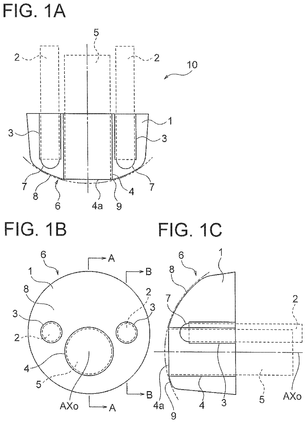
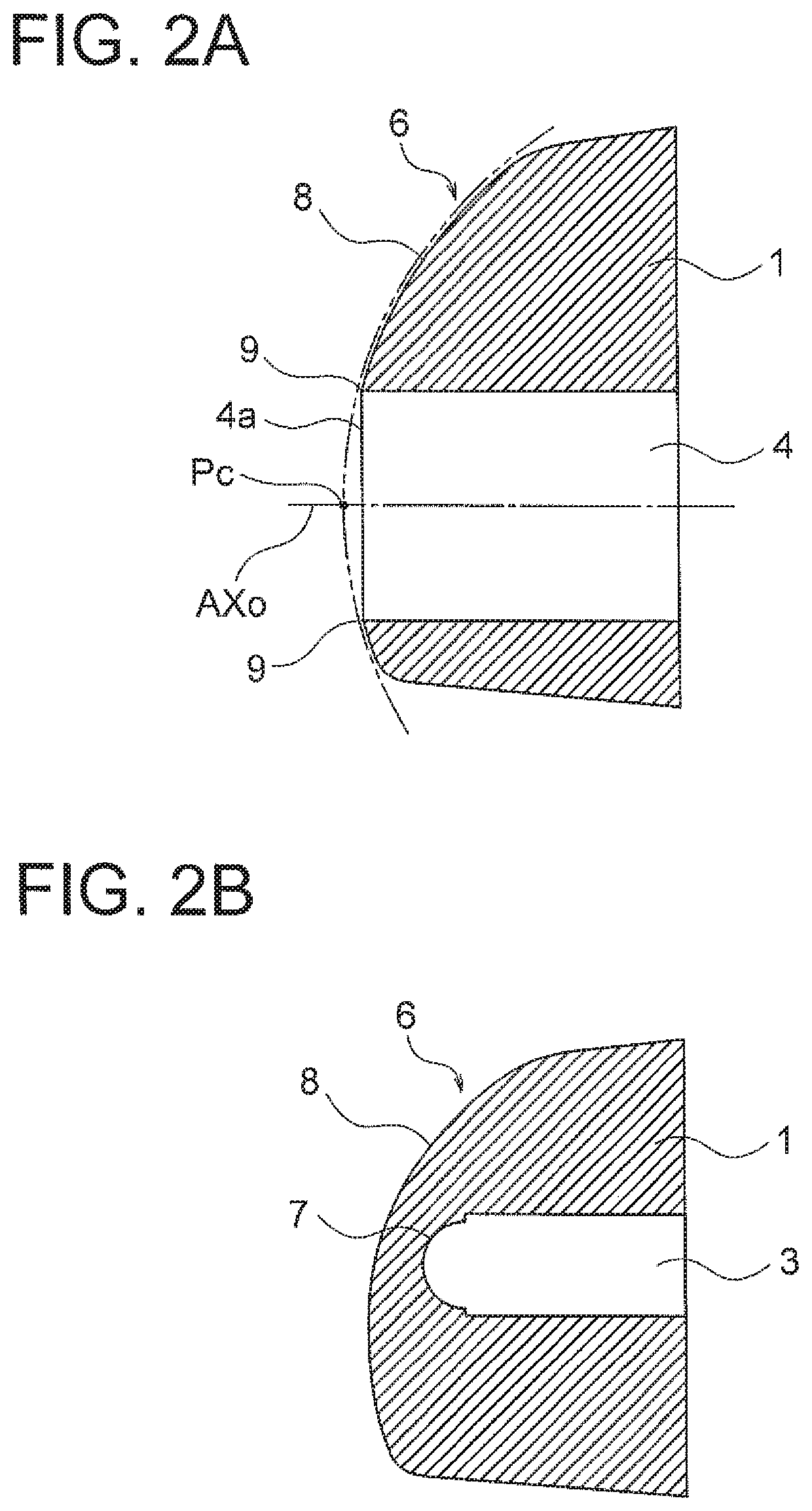
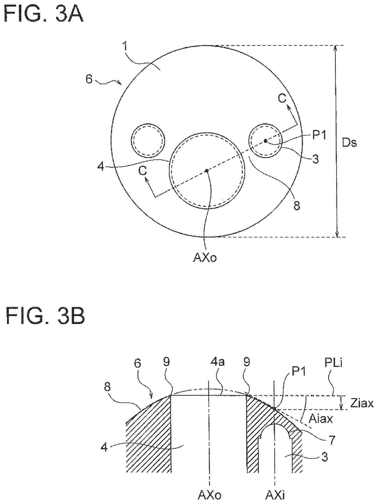
The endoscope illuminating optical system includes a transparent resin member, and a lighting member which outputs illumination light. The transparent resin member has a through hole in which an image sensor is disposed, a non-through hole in which the lighting member is disposed, an internal optical surface which is formed at an interior of the transparent resin member by the non-through hole, and an outer surface from which the illumination light incident on the transparent resin member via the internal optical surface, is emerged toward an object. The outer surface has a curved-surface area through which the illumination light passes, and the curved-surface area has a boundary with the through hole. In the curved-surface area, a displacement of each point of the curved-surface area from the boundary occurs in a direction away from the object.

Description

CROSS-REFERENCE TO RELATED APPLICATION[0001]The present application is a continuation application of PCT / JP2017 / 019028 filed on May 22, 2017 which is based upon and claims the benefit of priority from Japanese Patent Application No. 2016-120712 filed on Jun. 17, 2016; the entire contents of which are incorporated herein by reference.BACKGROUND OF THE INVENTIONField of the Invention[0002]The present invention relates to an endoscope illuminating optical system.Description of the Related Art[0003]As an endoscope intended for internal organs of urinary system, an endoscope for urinary organs is available. In the endoscope for urinary organs, for making an insertion into the urethra easy, it is preferable that an outer diameter be not more than 7 mm. In such manner, the outer diameter of the endoscope for urinary organs is smaller than an outer diameter of an endoscope for alimentary tract which is widely known for medical examination of stomach and large intestine. Moreover, the intern...

Claims


Application Information

Patent Timeline
Patent Type & Authority Patents(United States)
IPC IPC(8): A61B1/00A61B1/07A61B1/307G02B23/24G02B13/04A61B1/06
CPCA61B1/00096A61B1/00188A61B1/0669A61B1/0676A61B1/07A61B1/307G02B13/04G02B23/243G02B23/2469
Inventor IGARASHI, TSUTOMU
Owner OLYMPUS CORP
Learn More