Device for determining the anteversion angle

a technology of anteversion angle and device, which is applied in the direction of instruments, prosthesis, image enhancement, etc., to achieve the effect of reducing radiation amount and high benefi

Active Publication Date: 2022-02-22
STRYKER EURO OPERATIONS HLDG LLC
View PDF7 Cites 0 Cited by
  • Summary
  • Abstract
  • Description
  • Claims
  • Application Information

AI Technical Summary

Benefits of technology

[0007]It may be seen as an object of the invention to provide a device, a system and a method for determining the anteversion angle of a femoral shaft of a femur. It would be of high benefit to reduce the amount of radiation to which a patient is exposed during the determination of the anteversion angle and to have a more efficient way to directly evaluate the anteversion angle of the femur.
[0019]According to an embodiment of the invention, each landmark corresponds to a lowest point on each condyle, wherein the lowest point is the point of the condyle where the tangent through the lowest point has the largest possible distance from the shaft axis. Typically, the condyles are highly visible in image data of the femur. Since tissue and bone have a different transparency for X-ray radiation, the bone and the landmarks of the bone are highly visible in X-ray images. Therefore, also the lowest point of the condyles can be determined in an easy and reliable manner. The processing unit may determine the lowest point of the condyles automatically, by the means of image recognition, image processing and / or feature extraction. Thus, the processing unit can determine the landmarks of the bone, e.g. the condyles, the femur head or the shaft axis, by analysing the provided image data with image processing tools or feature extraction algorithms. The tangents placed through the lowest point of the condyles may be parallel to each other. Furthermore, the processing unit of the device may determine a distance between the two tangents in the image data. The distance may correlate with the accuracy of the anteversion angle determination. In other words, the larger the distance between the two tangents in the image data, the lower may be the accuracy of the determined anteversion angle. Therefore, it should be understood that the distance between the two condyles in the image data should not exceed a predefined threshold.
[0026]By providing two 2D images of a 3D object with different angles, the size as well as the shape of the 3D object can be determined. It may be possible to make two proximal images of the femur head, e.g. the first image as an AP image (anterior-posterior) and the second as an ML image (medio-lateral). With the two 2D images of the proximal situation, the centre of the femur head may be determined. The two tangents through the condyles may define a first plane. The centre of the femur head and the shaft axis of the femur shaft may define a second plane. The angle of intersection between the first plane and the second plane may correspond to the anteversion angle of the femoral shaft. The device according to the present invention may therefore be able to determine the anteversion angle of the femoral shaft based on only three 2D images of the femur, two proximal images and one distal image. It should be noted, that the device according to the present invention carries out automatically the method and the sole steps for determining the anteversion angle of the femoral shaft. Thus, a physician is not needed to identify the landmarks in the provided image data or to determine the anteversion angle of the femoral shaft. Typically, the two proximal images are already at hand due to the implantation of an implant, e.g. a bone nail. Thus, only one additional distal image of the femur has to be acquired and / or provided by an imaging unit and / or the provision unit to determine the anteversion angle of the femoral shaft. Therefore, the amount of radiation the patient is exposed to is greatly reduced.
[0028]Further, the distance between the two tangents in the provided image can be determined. If said distance exceeds a predefined threshold, the provision unit may acquire another distal image of the femur. Furthermore, it may be possible to minimize the distance between the two tangents in the provided image data to reduce the resulting error.

Problems solved by technology

In every surgery, where intraoperative imaging is used, it is a challenge to accurately perform the necessary steps of a procedure of treating a bone fracture.

Method used


Image

  • Device for determining the anteversion angle
  • Device for determining the anteversion angle
  • Device for determining the anteversion angle

Examples


Embodiment Construction

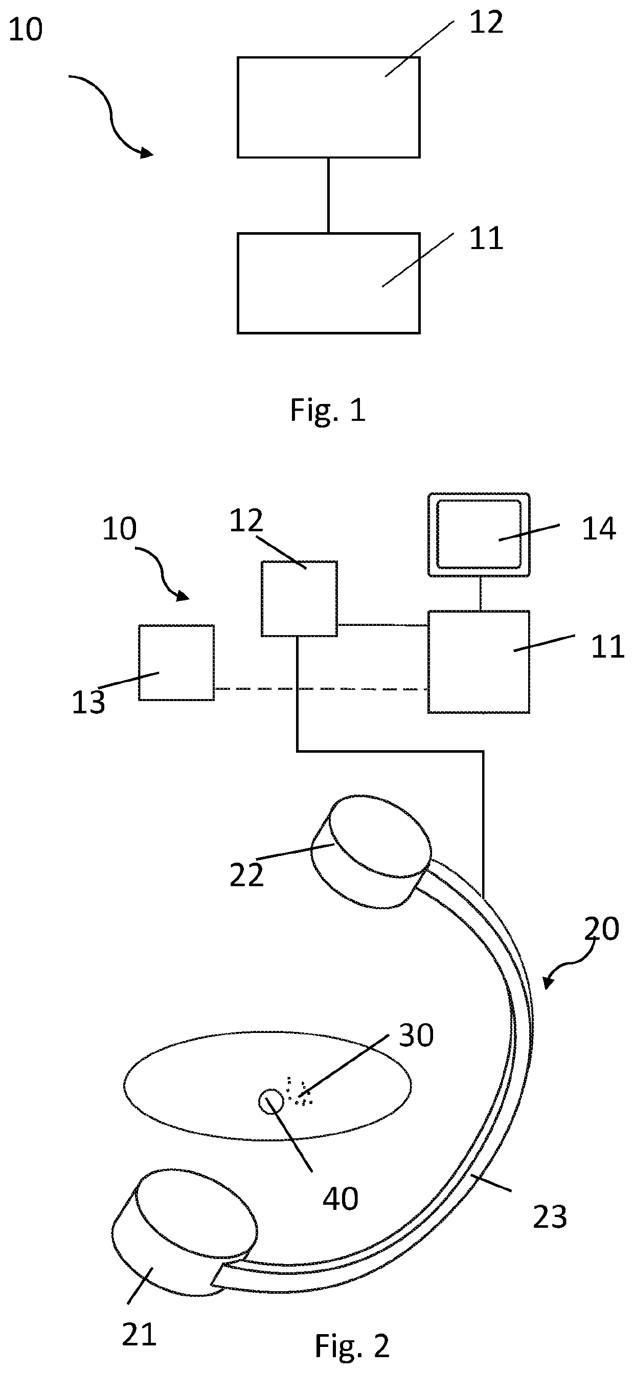
[0054]FIG. 1 illustrates an exemplary embodiment of a device 10 for determining the anteversion angle of a femoral shaft. The device 10 comprises a processing unit 11 and a provision unit 12. The provision unit 12 is configured to provide image data of the femur of which the anteversion angle should be determined. The processing unit 11 is configured to determine a longitudinal shaft axis through the femoral shaft based on the provided image data of the provision unit 12. The processing unit 11 further is configured to determine at least two landmarks of the femur and to place tangents through each one of the landmarks. The landmarks may be the condyles and / or the lowest point of the condyles. The processing unit 11 may determine the landmarks, e.g. the lowest point of the condyles, the femur head and / or the shaft axis through the femoral shaft, automatically, by the means of image recognition, image processing and / or feature extraction. Thus, the processing unit 11 analyses the pro...


PUM


Abstract

A device, a system and a method for determining an anteversion angle of a femoral shaft of a femur are provided. The device includes a provision unit and a processing unit. The provision unit is configured to provide image data of the femur, and wherein the processing unit is configured to determine a longitudinal shaft axis extending through the femoral shaft based on the image data. The processing unit is further configured to determine at least two landmarks of the femur based on the image data, and place a tangent trough each landmark parallel to the shaft axis. The processing unit is configured to determine the anteversion angle of the femoral shaft based on the tangents and the shaft axis of the femoral shaft.

Description

CROSS-REFERENCE TO RELATED APPLICATIONS[0001]The present application is a national phase entry under 35 U.S.C. § 371 of International Application No. PCT / IB2017 / 056407, filed Oct. 16, 2017, published in English, the disclosure of which is incorporated herein by reference.FIELD OF THE INVENTION[0002]The invention relates to the field of X-ray assistance for surgery. In particular, the invention relates to a device, a system and a method for determining the anteversion angle based on two tangents through two landmarks of the femur.BACKGROUND OF THE INVENTION[0003]In every surgery, where intraoperative imaging is used, it is a challenge to accurately perform the necessary steps of a procedure of treating a bone fracture. Usually, almost each step requires an iterative process based on several X-ray images. A significant radiation exposure is thus produced. The amount of radiation may be highly dependent on the know-how and skill of the physician.[0004]Some systems may provide virtual i...

Claims


Application Information

Patent Timeline
Patent Type & Authority Patents(United States)
IPC IPC(8): A61B6/00G06T7/73G16H50/30G16H30/40G06T7/60A61B90/00
CPCA61B6/505A61B6/5217G06T7/60G06T7/73G16H30/40G16H50/30A61B6/4441A61B2090/067G06T2207/10116G06T2207/30008A61B17/72A61F2002/4668A61B2090/3764
Inventor BLAU, ARNO
Owner STRYKER EURO OPERATIONS HLDG LLC
Why Eureka
Try Eureka