Eureka AIR delivers breakthrough ideas for toughest innovation challenges, trusted by R&D personnel around the world.

Control device of power switch

Active Publication Date: 2022-02-22
EXCELLIANCE MOS
View PDF8 Cites 0 Cited by
  • Summary
  • Abstract
  • Description
  • Claims
  • Application Information

AI Technical Summary

Benefits of technology

The patent is about a device that controls power switches. It reduces the chance of damage to the switch by measuring the voltage on the control end and the output end of the switch. The device then determines whether to discharge the control end of the switch based on the comparison. This way, the device prevents the voltage difference between the control end and the output end from being too great, which could cause damage to the switch. As a result, the device ensures the switch operates properly and without risking damage.

Problems solved by technology

This excessively high bias voltage may damage the power switch.
Under long-term working conditions, the power switch may even burn out.

Method used


Image

  • Control device of power switch
  • Control device of power switch
  • Control device of power switch

Examples


Embodiment Construction

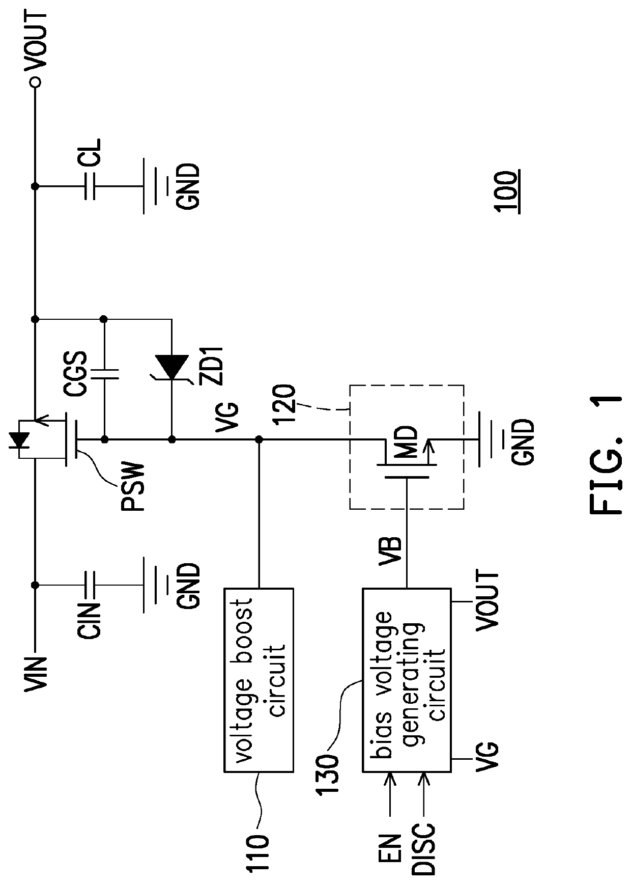
[0013]Referring to FIG. 1, FIG. 1 is a schematic view of a control device of a power switch according to an embodiment of the disclosure. A control device 100 is used to control the on and off actions of a power switch PSW. For example, the power switch PSW includes an N-type transistor. The first end of the power switch PSW receives an input voltage VIN, the second end of the power switch PSW generates an output voltage VOUT, and the control end of the power switch PSW receives a control voltage VG. Moreover, a capacitor CIN is coupled between the first end of the power switch PSW and a reference ground end GND, and a capacitor CL is coupled between the second end of the power switch PSW and the reference ground end GND. Both capacitors CIN and CL can be used as stabilized capacitors. A capacitor CGS is between the control end and the second end of the power switch PSW, and a Zener diode ZD1 is connected to the capacitor CGS in parallel. The anode of the Zener diode ZD1 is coupled ...


PUM


Abstract

A control device of a power switch includes a voltage boost circuit, a discharge circuit and a bias voltage generating circuit. The voltage boost circuit generates a control voltage at a control end of the power switch by boosting a base voltage. The discharge circuit provides a discharge path between the control end of the power switch and a reference ground end according to a bias voltage. The bias voltage generating circuit compares an output voltage on an output end of the power switch with the control voltage to generate a comparison result, and generates the bias voltage according to the comparison result.

Description

CROSS-REFERENCE TO RELATED APPLICATION[0001]This application claims the priority benefit of Taiwan application serial no. 110121054, filed on Jun. 9, 2021. The entirety of the above-mentioned patent application is hereby incorporated by reference herein and made a part of this specification.BACKGROUNDTechnology Field[0002]The disclosure relates to a control device of a power switch, and more particularly to a control device capable of preventing the power switch from being damaged.Description of Related Art[0003]In the conventional technical field, in electronic circuits, power switches are often disposed to control whether the power supply voltage is transmitted to the medium of the load device. When an electronic device is turned on, the power switch is turned on according to the received control signal, and the power voltage can be transmitted to the load device; in contrast, when the electronic device is turned off, the power switch is cut off according to the received control s...

Claims


Application Information

Patent Timeline
IPC IPC(8): H03K17/687H03K17/082H03K19/20H03K19/0185G05F3/26H03K17/18
CPCH03K17/0822G05F3/26H03K17/18H03K17/6871H03K19/018507H03K19/20H03K2217/0027
Inventor CHIEN, MING-HUNG
Owner EXCELLIANCE MOS
Why Eureka
Eureka Blog
Learn More