
Method for purifying (meth)acrylic esters

a technology of acrylic esters and purification methods, which is applied in the direction of chemical apparatus and processes, separation processes, organic chemistry, etc., can solve the problems of high capital cost, complex process, and high energy and capital cost of industrial plants, and achieves high energy and capital cost. cost, the effect of reducing the cost of capital cos

Active Publication Date: 2022-03-01
ARKEMA FRANCE SA
View PDF11 Cites 0 Cited by
  • Summary
  • Abstract
  • Description
  • Claims
  • Application Information

AI Technical Summary

Benefits of technology

The process achieves high purity (>99.5%) of C4-C12 (meth)acrylic esters with reduced energy consumption and minimized impurities, lowering capital costs and operational expenses compared to traditional methods.

Problems solved by technology

For these purposes, a separation / purification process, comprising a series of distillations, extractions and / or separations by settling, is generally carried out, which process is both relatively complex to carry out and expensive from an energy and capital cost viewpoint for an industrial plant.
It turns out that the process described in the document U.S. Pat. No. 7,268,251 is complicated to carry out on the industrial scale, as a result of the optimization of the operating conditions of the sequence of the four distillation / rectification elements, in order to obtain a product of high purity and a satisfactory output.
This process, which is very expensive in capital costs, additionally requires a large surface area for installation.
However, the purification process described in this document is applicable to the production of aminoalkyl (meth)acrylates and does not solve the question of the preliminary separation of the catalyst when the esters are sensitive to retrogradation reactions.
In particular, the presence of the catalyst in the divided wall column risks bringing about cracking reactions resulting in the formation of compounds which contaminate the purified product drawn off as a sidestream.
However, the different configurations described relate solely to the expected energy saving, and the state of the art in its entirety does not in the least suggest the type of configuration suitable for the purification of crude (meth)acrylic reaction mixtures resulting from a catalytic transesterification reaction.

Method used


Image

  • Method for purifying (meth)acrylic esters

Examples


example 2 (comparative)

stillation Columns in Series and Sidestream Withdrawal of the Purified Product

[0111]A crude DAMEA reaction mixture resulting from the synthesis by transesterification of ethyl acrylate and dimethylaminoethanol was subjected to a purification treatment using two distillation columns in series.

[0112]The first column comprises an equivalent, in theoretical stages, of 9 and it is combined at the bottom with a boiler and at the top with a condenser in which an organic phase is recycled partly in the column in order to provide the column with a reflux. The column is stabilized by injection of PTZ at the top condenser. The energy supplied by the boiler is 0.74 MW.

[0113]The second column comprises an equivalent, in theoretical stages, of 16 and it is combined at the bottom with a boiler and at the top with a condenser. It is fed by the bottom stream from the first column, which comprises the DAMEA, and also the light products (EA, DMAE) and heavy byproducts, such as the Michael adducts. The...

example 3 (

According to the Invention)

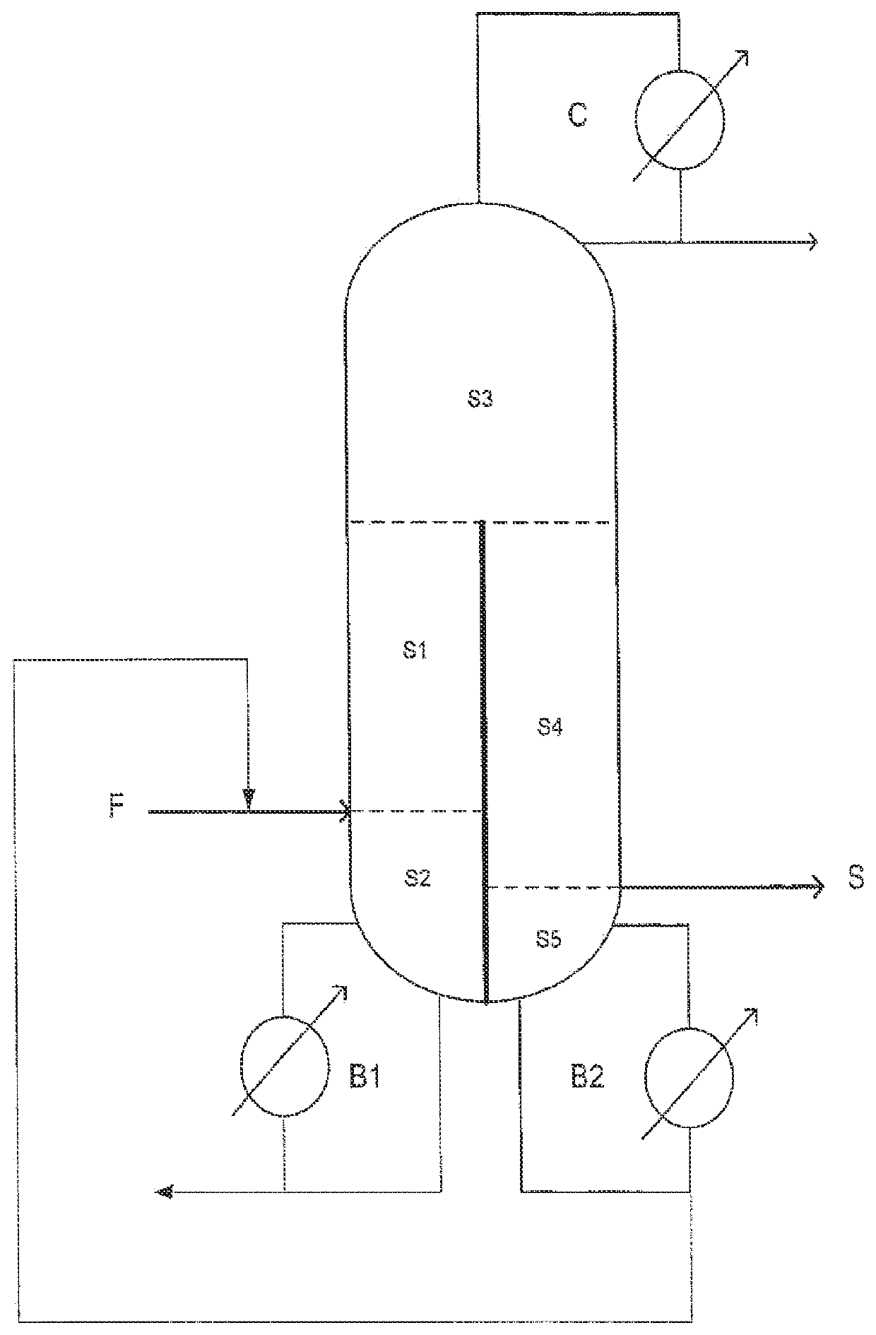
[0123]An ASPEN simulation using a thermodynamic model was carried out on the crude DAMEA reaction mixture, as described in examples 1 and 2, but subjected to a purification using the purification system as represented in the FIGURE.

[0124]In this example, the divided wall column is stabilized at the top condenser with PTZ and the DAMEA withdrawn as a sidestream in the gas phase is stabilized with HQME.

[0125]In this configuration, the number of plates of the different sections is as follows:[0126]N1: 8—N2: 6—N3: 5—N4: 10—N5: 1.

[0127]The energy supplied by the boiler is 1.4 MW.

[0128]The purified product withdrawn as a sidestream has the following composition by weight:[0129]DAMEA: 99.8%—DMAE: traces[0130]AAP traces—AEP: 237 ppm—EEP: 919 ppm—heavy products, including AEP: 254 pm[0131]Total stream: 2870 kg / h—temperature: 110° C.—pressure: 0.118 bar

[0132]In this configuration, the DAMEA is recovered with a yield of the order of 88%, with respect to the feed stre...

example 4

on of the Bottom Product During the Distillation

[0136]The aim of this example is to show the importance of the positioning of the separating wall in the divided wall column for the quality of the product obtained in sidestream withdrawal, in particular the need to have a wall separating the bottom part of the column.

[0137]We used a laboratory assembly composed of a stirred reactor, of a distillation column and of an oil bath which makes it possible to heat the product to the desired temperature.

[0138]A mixture having a composition close to the composition expected at the bottom of the distillation column at the boiler B1 was introduced into the reactor and subjected to a temperature of 140° C. at P atm for 3 hours.

[0139]The distillate collected at the top of the distillation column and the distillation bottom product were subsequently analyzed.

[0140]The amounts by weight of the light products distilled, in comparison with the amounts present in the mixture introduced into the reacto...


PUM

PropertyMeasurementUnit
pressureaaaaaaaaaa
temperatureaaaaaaaaaa

Abstract

The invention relates to the production of (meth)acrylic esters according to a continuous process by transesterification, and in particular to the purification of a crude reaction mixture comprising a C4-C12 (meth)acrylic ester using a divided wall column employed in a particular configuration. This configuration results in a simplification of the purification process with a reduced energy consumption and a minimized content of impurities present in the purified (meth)acrylic ester. The invention also relates to a process for the production of C4-C12 (meth)acrylic ester comprising this recovery / purification process.

Description

CROSS-REFERENCE TO RELATED APPLICATIONS[0001]This application is a national stage application under 35 U.S.C. § 371 of PCT / FR2018 / 051645, filed Jul. 3, 2018 which claims benefit to application FR17.57038, filed Jul. 25, 2017.TECHNICAL FIELD[0002]The present invention relates to the production of (meth)acrylic esters according to a continuous process by transesterification, and in particular to the purification of a crude reaction mixture comprising a C4-C12 (meth)acrylic ester using a divided wall column employed in a particular configuration.[0003]This configuration results in a simplification of the purification process with a reduced energy consumption and a minimized content of impurities present in the purified (meth)acrylic ester.[0004]The invention also relates to a process for the production of C4-C12 (meth)acrylic ester comprising this recovery / purification processTechnical Background and Technical Problem[0005]C4-C12 (meth)acrylic esters are generally synthesized by transe...

Claims


Application Information

Patent Timeline
Patent Type & Authority Patents(United States)
IPC IPC(8): C07C67/54C07C67/02
CPCC07C67/54C07C67/02B01D3/141C07C67/03C07C213/06C07C213/10C07C69/54C07C219/08
Inventor ROLEZ, ELOITRETJAK, SERGE
Owner ARKEMA FRANCE SA
Learn More