Method and apparatus for desolvating flowing liquid

a technology of flowing liquid and apparatus, applied in liquid degasification, separation processes, instruments, etc., can solve problems such as thermal degradation or volatile-solute evaporation conditions, and achieve the effects of reducing the amount of remaining solvent vapor, limiting the validity or scope of claims, and small siz

Active Publication Date: 2014-08-14
SPECTRA ANALYSIS INSTR INC
View PDF0 Cites 3 Cited by
  • Summary
  • Abstract
  • Description
  • Claims
  • Application Information

AI Technical Summary

Benefits of technology

This patent describes a system for treating liquid streams to remove solutes while keeping them in a soluble state. The system uses a nebulizer to convert the liquid stream into a high-speed aerosol jet, which is then directed into a hot chamber where the solvent evaporates. The evaporation process causes the solute to film boil, which prevents it from contacting the chamber wall and allows it to be carried out of the chamber with the gas stream. The system can handle a wide range of starting droplet sizes and automatically adjusts the heat input to each droplet to evaporate the solvent. The residual solvent is removed through a condensation process, and the system can also protect the sample from thermal degradation. The invention allows for further processing of the particulate stream, such as directing it onto a window or membrane.

Problems solved by technology

Because the residence time of a droplet in the cyclone is inversely related to the starting droplet size, the result is minimal exposure of each droplet to high temperature, potentially thermally degrading or volatile-solute evaporating conditions.

Method used


Image

  • Method and apparatus for desolvating flowing liquid
  • Method and apparatus for desolvating flowing liquid
  • Method and apparatus for desolvating flowing liquid

Examples


Embodiment Construction

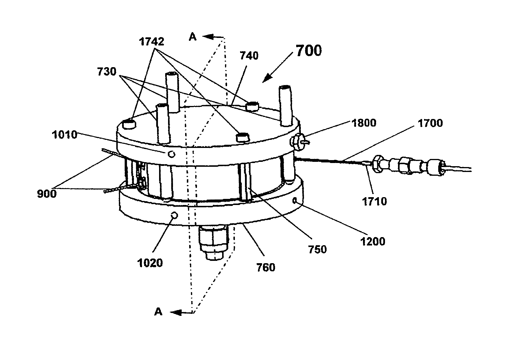
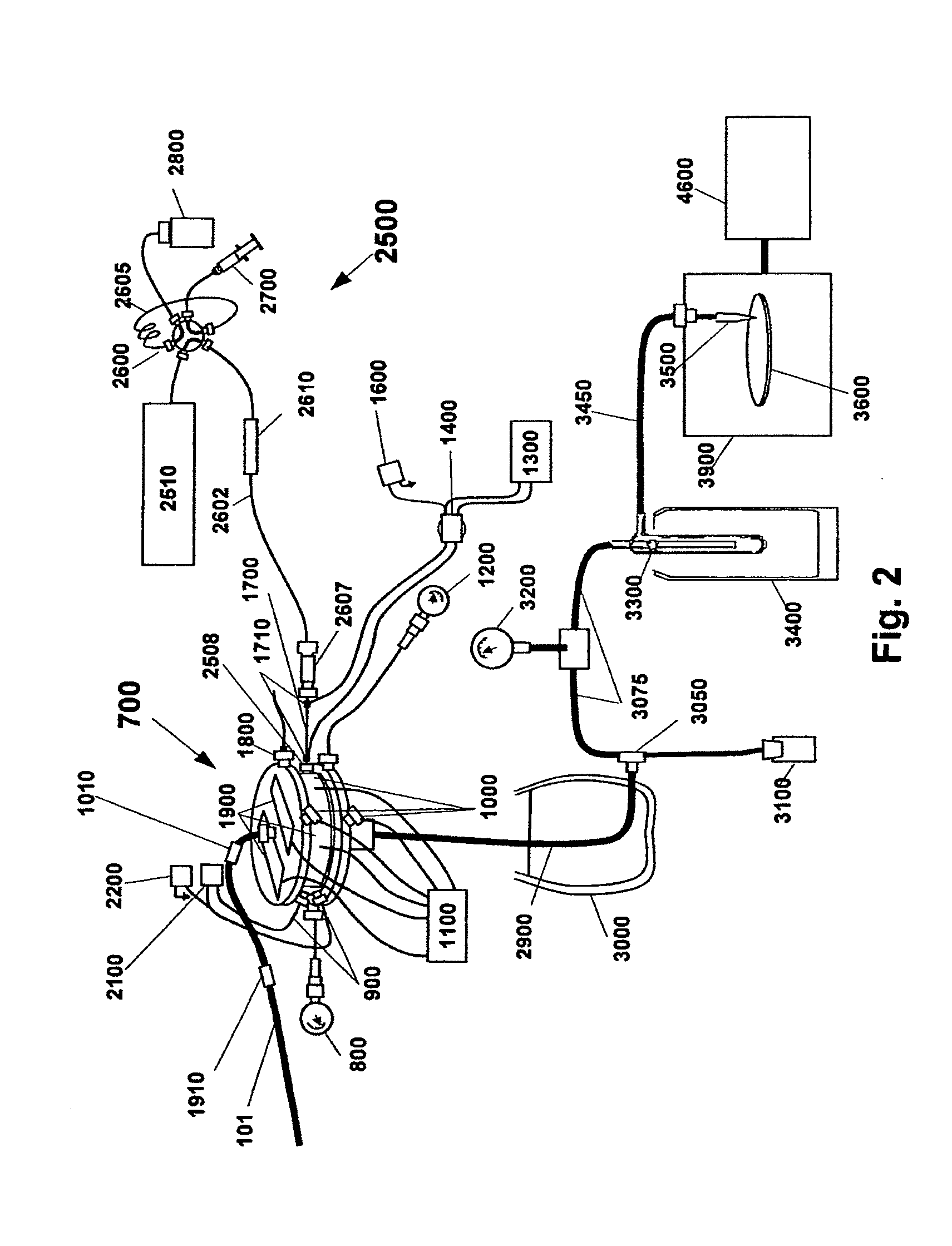
[0156]The present invention discloses methods and apparatus as schematically illustrated in FIG. 2, which illustrates a simplified version of an apparatus according to this invention for desolvating flowing liquid streams while retaining temporal separation of dissolved solutes. LC techniques are generally well known in this art. As shown in FIG. 2, an isocratic or gradient Liquid Chromatography (LC) system 2500 is provided consisting of LC pump 2510, injector 2600 with associated sample loop 2605, sample loading syringe 2700 and waste bottle 2800. The LC system delivers the combined sample and solvent stream into chromatography column 2610. The LC eluent flows through capillary 2602 connected by compression fitting union 2607 to electrically heated thermal nebulizer 1700. The nebulizer 1700 is connected to cyclone 700 by compression fitting 2508. Sample travels from the cyclone 700 through the first-stage condenser tube 2900 to tee 3050 where condensed solvent drains into waste bot...


PUM


Abstract

Methods and apparatus for desolvating flowing liquid streams while retaining temporal resolution of dissolved substrates are disclosed. A novel small-scale self-regulating spray dryer preserves temporal resolution while desolvating a liquid chromatography eluent stream and depositing the solute onto an optical surface for infrared spectrographic analysis. The liquid eluent is pumped through a heated nebulizer to create a high-speed jet of solute containing liquid and solvent vapor. This jet is directed circumferentially inside a hot cylindrical cavity. Centrifugal force causes the larger liquid droplets to travel along the outer diameter of the cavity. The cavity surface is heated to cause the droplets to film boil. Film boiling reduces droplet contact with the cavity surface thereby retaining the solute in the droplets. The solute temperature is limited by controlling the pressure into which the solvent evaporates from the droplets. When the droplets are sufficiently small, Stokes drag from the exiting solvent vapor carries the droplets out through the center of the cylindrical cavity. After exiting, the superheated solvent vapor further dries the droplets. Solvent vapor is removed by condensation onto a cooled surface. A freezing point reducing agent may be added to improve removal of solvent condensate. Stokes drag from a non-condensable gas maintains the dried droplets in suspension. This suspension travels through an orifice that focuses the impaction of the dried droplets onto the optical surface for infrared analysis. The deposition surface is in an evacuated chamber and is temperature controlled to freeze liquid solutes yet allowing sublimation of residual solvent.

Description

CROSS-REFERENCE TO RELATED APPLICATIONS[0001]This application is a Division of U.S. Ser. No. 12 / 312,890 filed May 29, 2009 (now pending), which is a Sec. 371 of PCT / US2007 / 025,207 filed Dec. 8, 2007, which claims the benefit of the filing dates of U.S. Provisional patent applications U.S. Ser. No. 60 / 873,848 filed Dec. 8, 2006 and U.S. Ser. No. 60 / 927,646 filed May 4, 2007. Each of these earlier related applications is incorporated herein by reference.FIELD OF INVENTION[0002]This invention relates generally to techniques and apparatus for desolvating flowing liquid streams while retaining structural integrity and temporal separation of dissolved solutes. More particularly, this invention relates to apparatus and methods for interfacing liquid chromatography with a Fourier transform infrared spectrometer which is applicable to continuous flow use in normal phase, reverse phase and size exclusion separations.BACKGROUND OF THE INVENTION[0003]A high degree of compound separation, select...

Claims


Application Information

Patent Timeline
Patent Type & Authority Applications(United States)
IPC IPC(8): B01D1/22
CPCB01D1/222B01D1/0094B01D1/16B01D19/0026B01D19/0052B01D19/0057G01N30/84G01N2030/743G01N2030/8494Y10T436/111666Y10T436/255Y10T436/25875
Inventor CARSON, WILLIAM W.BOURNE, SIDNEY
Owner SPECTRA ANALYSIS INSTR INC
Why Eureka
Try Eureka