Low pressure fluctuation apparatuses for blending fluids, and methods of using the same

a technology of low pressure fluctuation and fluid blending, which is applied in non-electric variable control, process and machine control, instruments, etc., can solve the problems of low pressure variation in the process, and achieve the effect of reducing pressure fluctuation, reducing pressure fluctuation, and eliminating pressure fluctuation

Active Publication Date: 2022-03-08
VERSUM MATERIALS US LLC
View PDF17 Cites 2 Cited by
  • Summary
  • Abstract
  • Description
  • Claims
  • Application Information

AI Technical Summary

Benefits of technology

[0012]The invention provides an improved apparatus and method to supply a (volumetric liquid) flow controller with low pressure fluctuation. The invention comprises a pump and a flow controller. The pump has closed-loop flow rate control. The pump flow rate control helps eliminate pressure fluctuation. The pump may be a low pressure fluctuation pump and / or a pump in series with a pressure regulator. The pump flow capacity may be in a certain ratio with the pressure regulator for pressure fluctuation to be reduced effectively.

Problems solved by technology

Conversely, without the apparatus adjustable characteristics, the process would not provide low pressure variation.

Method used


Image

  • Low pressure fluctuation apparatuses for blending fluids, and methods of using the same
  • Low pressure fluctuation apparatuses for blending fluids, and methods of using the same
  • Low pressure fluctuation apparatuses for blending fluids, and methods of using the same

Examples


first embodiment

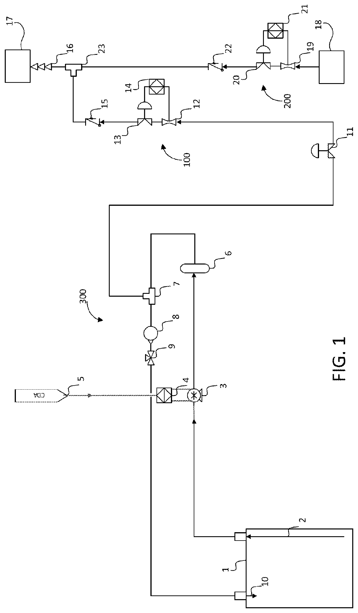
[0081]The pump 3a is connected via a tube to an optional filter housing 6. The filter housing is the same as described in the

[0082]The filter housing 6 is connected via a tube to dome loaded pressure regulator 30. A useful regulator is available from SMC with a flow capacity of 40 LPM. (In other embodiments, the volumetric flow capacity of the regulator may be approximately 20 to 50 LPM). This compares with pump 3a maximum volumetric flow rate 2.5 GPM (9.5 LPM), a ratio of approximately 4:1. In other embodiments, this ratio may be from 2.5:1 to 5.5:1 or from 3:1 to 5:1 or 3.5:1 to 4.5:1. The maximum pressure (pilot and liquid) is 0.5 MPa, with 0.4 MPa (pilot and liquid) being practical nominal operating maximum pressures. The optimum pilot pressure range for maximum pressure fluctuation suppression is 0.15+ / −0.05 MPa. The lower the pilot pressure, the better the pressure fluctuation (of the liquid) is suppressed. The pilot pressure controls the valve opening %; lower pressure causes...

second embodiment

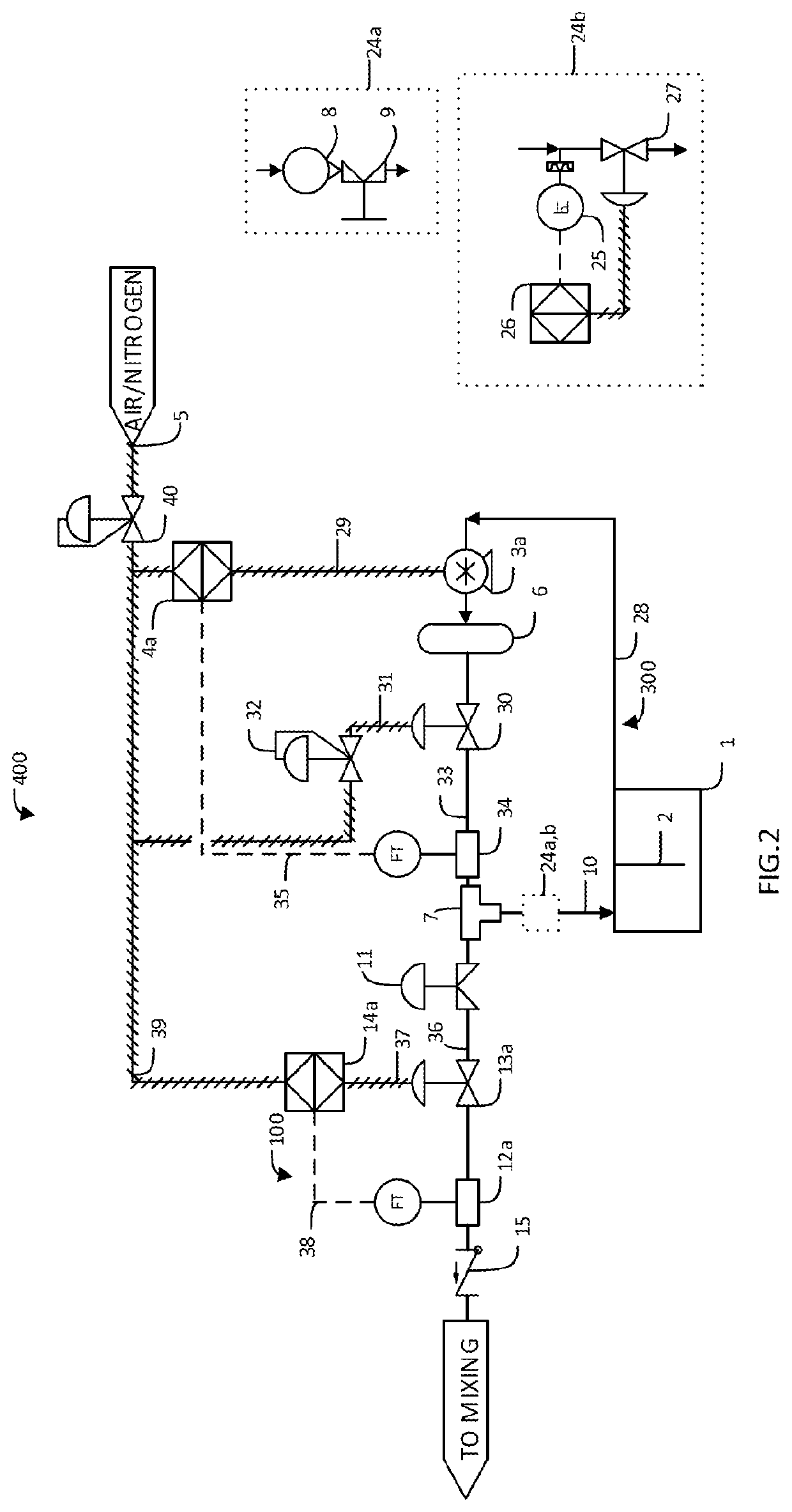
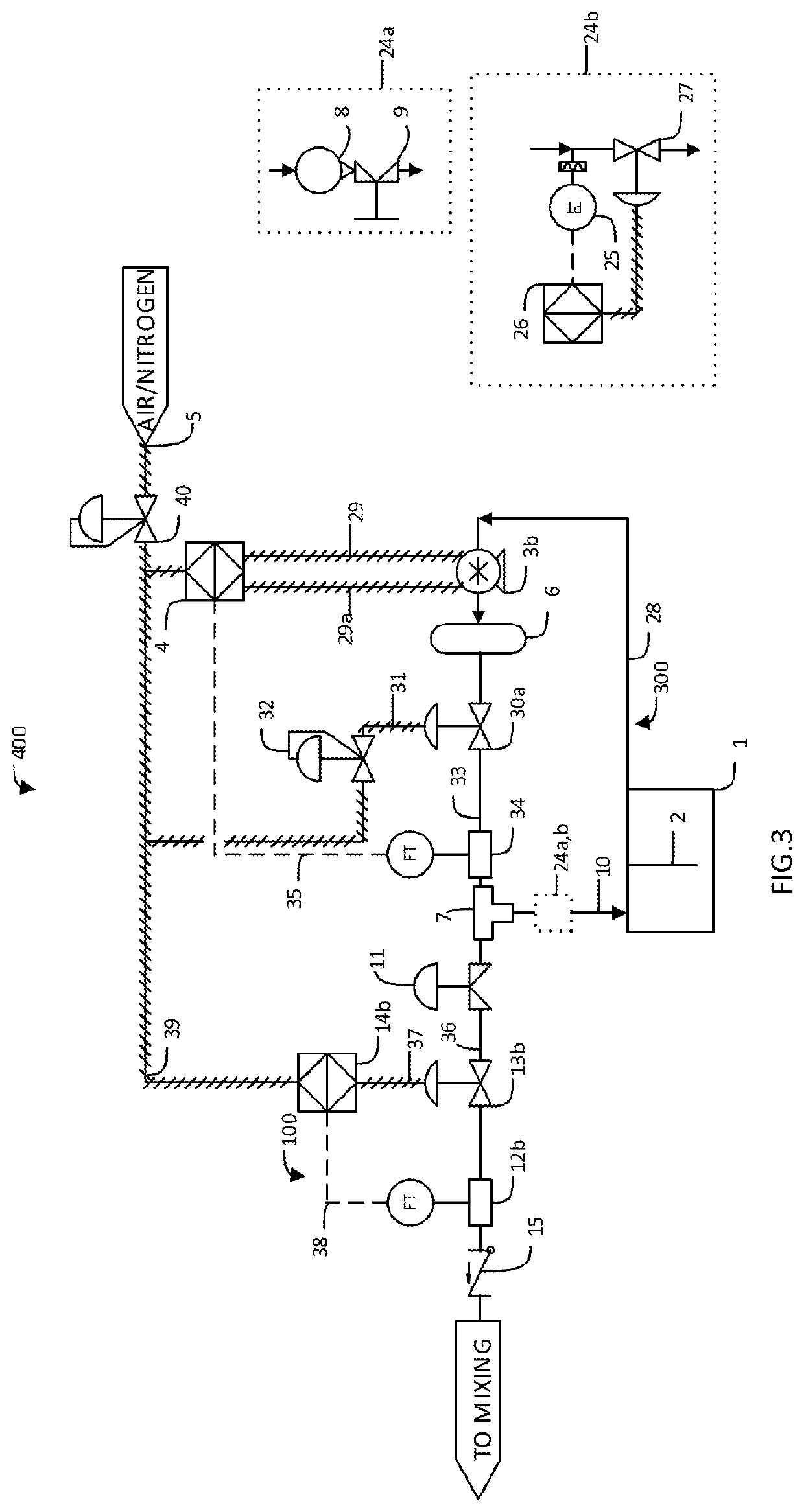
[0109]Tube 36 provides fluid to the regulator 13b and flow meter 12b. The tube size may preferably be ⅜″ outer diameter. Tube 36 is connected to dome loaded pressure regulator 13b. A preferred regulator is from SMC with a flow capacity of 15 LPM. The maximum pressure (pilot and liquid) is 0.5 MPa, with 0.4 MPa (pilot and liquid) being practical nominal operating maximum pressures. The optimum pilot pressure range for maximum pressure fluctuation suppression is 0.15+ / −0.05 MPa. Regulator 13b will obtain higher flow rates operating at 0.1-0.2 MPa pilot pressure than regulator 13a of the second embodiment shown in FIG. 2, while operating in an effective pilot pressure range for pressure fluctuation suppression. This regulator 13b constitutes the third stage of pressure fluctuation suppression. In this embodiment, the effect of the pressure fluctuation suppression will be measured by the flow meter 122b, downstream of the pressure regulator 13b.

[0110]The regulator is connected to contr...


PUM

PropertyMeasurementUnit
response timeaaaaaaaaaa
velocityaaaaaaaaaa
pressureaaaaaaaaaa

Abstract

A low pressure fluctuation control apparatus comprises a liquid recirculation loop comprising a dip tube, a diaphragm or bellows type pump, a first regulator, a first flow meter, a junction, and a return tube. A back pressure controller is located in the return tube. In addition, the apparatus comprises a material supply line fluidly connected the liquid recirculation loop via the junction. A flow control system is located in the material supply line. The recirculation loop draws liquid from a supply container by the dip tube, and returns a portion of the liquid to the supply container by the return tube. The backpressure flow controller regulates the flow rate of the liquid, thereby steadying fluctuations in the liquid being supplied.

Description

[0001]This application claims the benefit of priority under 35 U.S.C. § 119(e) to earlier filed U.S. patent application Ser. No. 62 / 061,538, filed on 8 Oct. 2014, having the title “Slurry Supply Apparatus and Method”, which is entirely incorporated herein by reference.BACKGROUND OF THE INVENTION[0002]There are several blending techniques commonly employed to blend ingredients for use in a semiconductor fabrication facility. Ingredients may include one or more of the following: liquids such as water, CMP slurry (abrasives and water or other diluent), hydrogen peroxide, acids, bases and other chemicals. The common blending methods include scale blending, which uses a scale having load cells to weigh ingredients in a mix tank. Another common method is beaker blending, which uses volumetric vessels to measure ingredients, that are then transferred from the volumetric vessels to a mix tank. A final common method is flow controller blending, which uses flow controllers to measure ingredie...

Claims


Application Information

Patent Timeline
Patent Type & Authority Patents(United States)
IPC IPC(8): B01F5/10G05D7/06G05D11/13B01F3/04B01F3/08B01F15/00G01F1/34
CPCB01F5/106B01F3/04985B01F3/088B01F3/0861B01F15/00149B01F15/00357B01F15/00974G01F1/34G05D7/0635G05D7/0647G05D7/0688G05D11/132B01F2215/0096B01F23/29B01F25/53B01F23/45B01F23/49B01F35/187B01F35/2213B01F35/21112B01F2101/58
Inventor BAYER, BENJAMIN PATRICKCHAN, LAURA SUK CHONGEREIFEJ, FADY KHALILROYBAL, DANIEL VALENTIN
Owner VERSUM MATERIALS US LLC
Why Eureka
Try Eureka