Hay baler

a baler and hay technology, applied in baling, agriculture tools and machines, agriculture, etc., can solve the problems of increasing production costs, increasing production costs, and increasing the cost of hay bales

Active Publication Date: 2022-03-29
AWG ENTERPRISE LLC
View PDF7 Cites 1 Cited by
  • Summary
  • Abstract
  • Description
  • Claims
  • Application Information

AI Technical Summary

Benefits of technology

[0012]While the unique compression chamber and overhead baling chamber configuration will provide a significant improvement in the performance of a baling chamber with one exit, the device herein provides additional utility when configured with a baling chamber having two bale forming sections, on opposite sides of a plunger. The plunger is operatively engaged to translate back and forth within the bale chamber to thereby form bales both on a first end of the baling chamber and on an opposite second end of the baling chamber. It should be noted however that the disclosed belt-driven and formed compression passage, may also be employed in a conventional hay baler, which compresses bales in only one end of a bale chamber and would provide significant speed and feeding utility over conventional material feeding components to a baler.
[0034]It is an object of this invention, to provide a baler, which operates to compact, tie, and discharge formed and tied bales, in a bidirectional baling chamber, thereby significantly increasing production.

Problems solved by technology

However, conventional bales produced in this round or rolled fashion can become large and very heavy and due to their shape are prone to rolling.
Various limitations of the related art will become apparent to those skilled in the art upon a reading and understanding of the specification below and the accompanying drawings.

Method used


Image

  • Hay baler
  • Hay baler
  • Hay baler

Examples


Embodiment Construction

[0052]In this description, the directional prepositions of up, upwardly, down, downwardly, front, back, top, upper, bottom, lower, left, right and other such terms refer to the device as it is oriented and appears in the drawings and are used for convenience only, and they are not intended to be limiting or to imply that the device has to be used or positioned in any particular orientation.

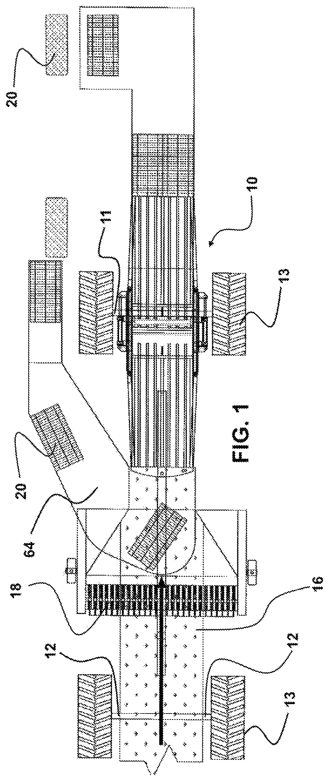
[0053]Now referring to drawings in FIGS. 1-12, wherein similar components are identified by like reference numerals, there is seen in FIG. 1, an overhead view of the baling device 10 herein, operatively engaged to a powered pulling component such as a tractor 12. Power for operation of the device 10 herein can be provided from the output shaft of the tractor 12 which is not shown but well known, and / or by onboard internal combustion engines and / or electric generators and / or pumps and the like, which are all well known and need not be depicted.

[0054]As shown in FIG. 1, a pickup mechanism 18 such as...


PUM


Abstract

A baler for hay, straw, grass, and similar feed materials is provided. The baler communicates compressed material from a vertically inclined compression passage formed in-between opposing conveyer belts to a central area of a baling chamber for baling. A plunger within the baling chamber can reciprocate in two directions to form bales which are tied and discharged from both ends of the baling chamber.

Description

BACKGROUND OF THE INVENTION1. Field of the Invention[0001]The present invention relates generally to baling devices employed to bale hay, straw, and similar crops and for other materials which are baled for transport and storage. More particularly, it relates to a baler device with a stacked configuration between gathered material and a baler chamber which can operate to bale such materials and crops using a bidirectional or reciprocating system.2. Prior Art[0002]It is a common practice to feed animals hay and similar harvested crops. Most such feed material is baled upon being cut, or soon thereafter, in order to provide compact storage and to render it more easily transportable. One common type of baler, in industrialized countries today, is the round baler. It produces cylinder-shaped “round” or “rolled” bales. When the rolled bale reaches a predetermined size, a flexible constraint such as netting or twine is wrapped around it to hold its shape, and the rear of the baler swings ...

Claims


Application Information

Patent Timeline
Patent Type & Authority Patents(United States)
IPC IPC(8): A01F15/10A01F15/04B30B9/30
CPCA01F15/101A01F15/042A01F15/046B30B9/3092A01F2015/102A01F2015/103A01F2015/108A01F15/06
Inventor ALLEY, JACK DWHITAKER, JAMESGOMES, GARY G
Owner AWG ENTERPRISE LLC
Why Eureka
Try Eureka