Sensor fastener arrangement

a technology of fastener and sensor, which is applied in the direction of shock absorbers, vessel construction, wind-induced force reduction, etc., can solve the problems of less useful information, significant error, and useless measurement data, and achieve the effect of reducing the load required for further deformation and reducing the acceleration of the sensor device when the fastener elements reversibly deform

Active Publication Date: 2022-03-29
SAAB AB
View PDF9 Cites 1 Cited by
  • Summary
  • Abstract
  • Description
  • Claims
  • Application Information

AI Technical Summary

Benefits of technology

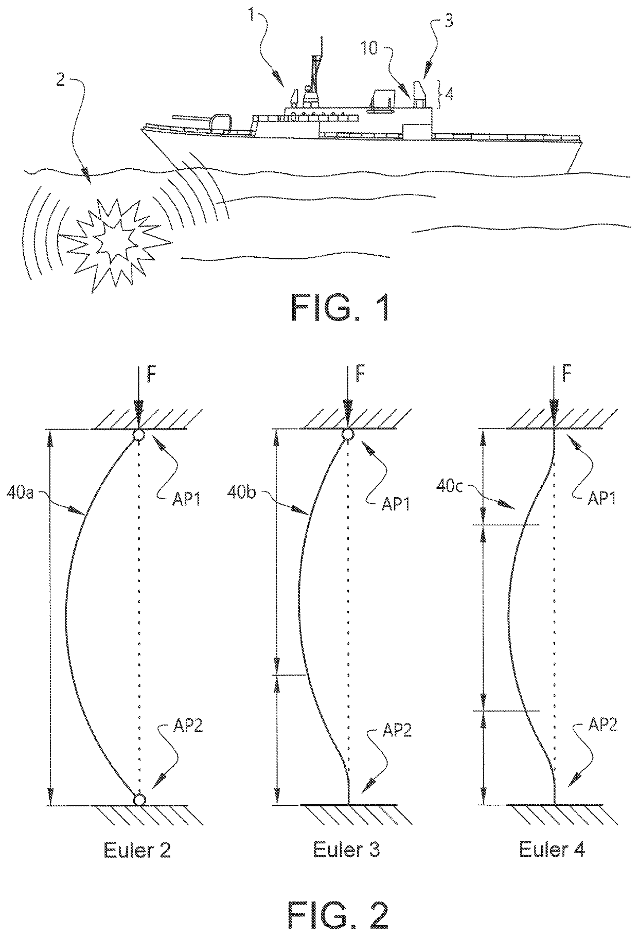
[0011]Sensor devices such as for example antennas, radars, rangefinders and aiming devices such as sights generally comprise sensitive electronics connected in complex networks. At the same time, in order for such sensor devices to operate properly and provide useful sensor data it is generally important that the sensor device is tightly secured at a known location and that the positioning of the sensor device is fixed. Even the smallest spatial dislocation or displacement of the sensor device may deteriorate the measurement data provided by the sensor device and may even make measurement data provided useless. A small displacement of an aiming device such as a sight may for example give a significant error over distance and a small spatial dislocation of an antenna such as a phased array antenna may provide less useful information, if not compensated for. Thus, sensor devices, and their installations, are very sensitive to impact force. Impact force is herein defined as a significant and temporary force, i.e. impact force is a force that delivers a shock or high impact in a relatively short period of time. Impact force is for example what a ship is exposed to if an underwater mine detonates in the vicinity of the ship at sea.
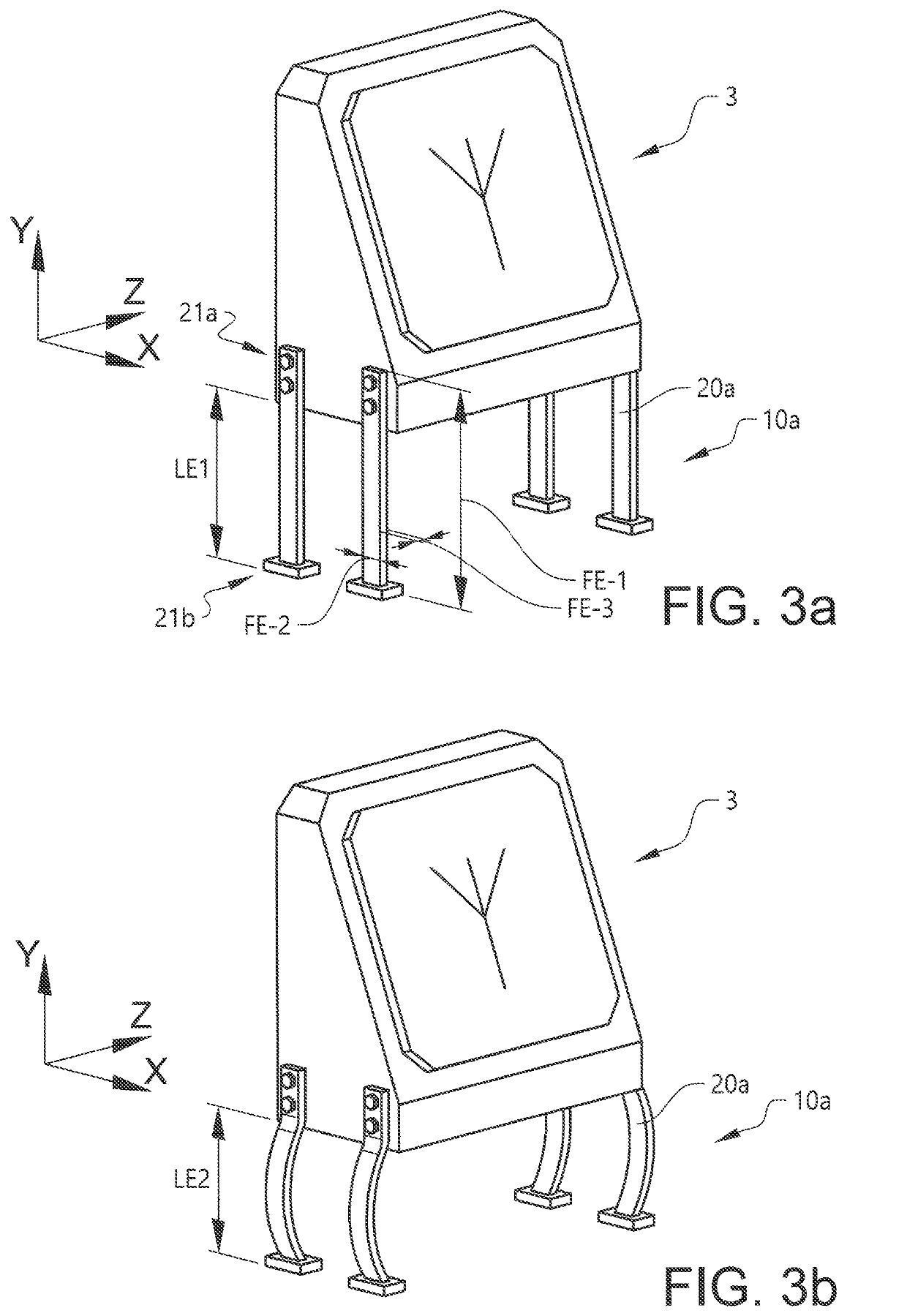
[0015]According to the invention, respective fastener element is deformed when the platform, to which the sensor device is arranged, and / or the sensor device itself is exposed to an impact force, in turn resulting in that the fastener element is exposed to a compressive force, exceeding a critical load. All fastener elements of a sensor fastener arrangement may either deform, i.e. go to the second state, at the same critical load or may deform at different critical loads. This is a design parameter dependent on the individual realization of the sensor fastener arrangement and will be discussed more in the detailed description of exemplary embodiments of the invention. The deformation of the fastener element at least partially absorbs the shock effect of the impact force whereby the actual force the sensor device is exposed to is limited. Thus, the invention has the exemplary advantage that a sensitive sensor device can be protected from impact force which possibly otherwise would be damaging for the sensor device.
[0020]Every sensor device, such as for example a sight or a specific antenna, is designed to withstand a defined impact force. This can be referred to as the maximum acceleration limit of the sensor device, or to as the the critical sensor device impact acceleration. High resistance to impact shock may for example be obtained by using components of thicker or more durable goods, making soldering thicker and by adding additional components with the single purpose of increasing durability or strength. This generally adds cost, weight and also makes the components, and thereby installations of components, more bulky. Thereby, generally, the higher impact shock a sensor device is configured to withstand the heavier and more costly it is. Thus, an exemplary advantage with the development of the invention is that by selecting the critical load of the fastener elements such that the fastener elements with certainty deform before the sensor device is exposed to the maximum acceleration limit, the sensor device is protected. Further exemplary advantages are that for a certain implementation a sensor device designed to withstand lower impact shock, possibly being less costly, have lower weight and be less bulky, may be selected if a sensor fastener arrangement according to the invention is used.
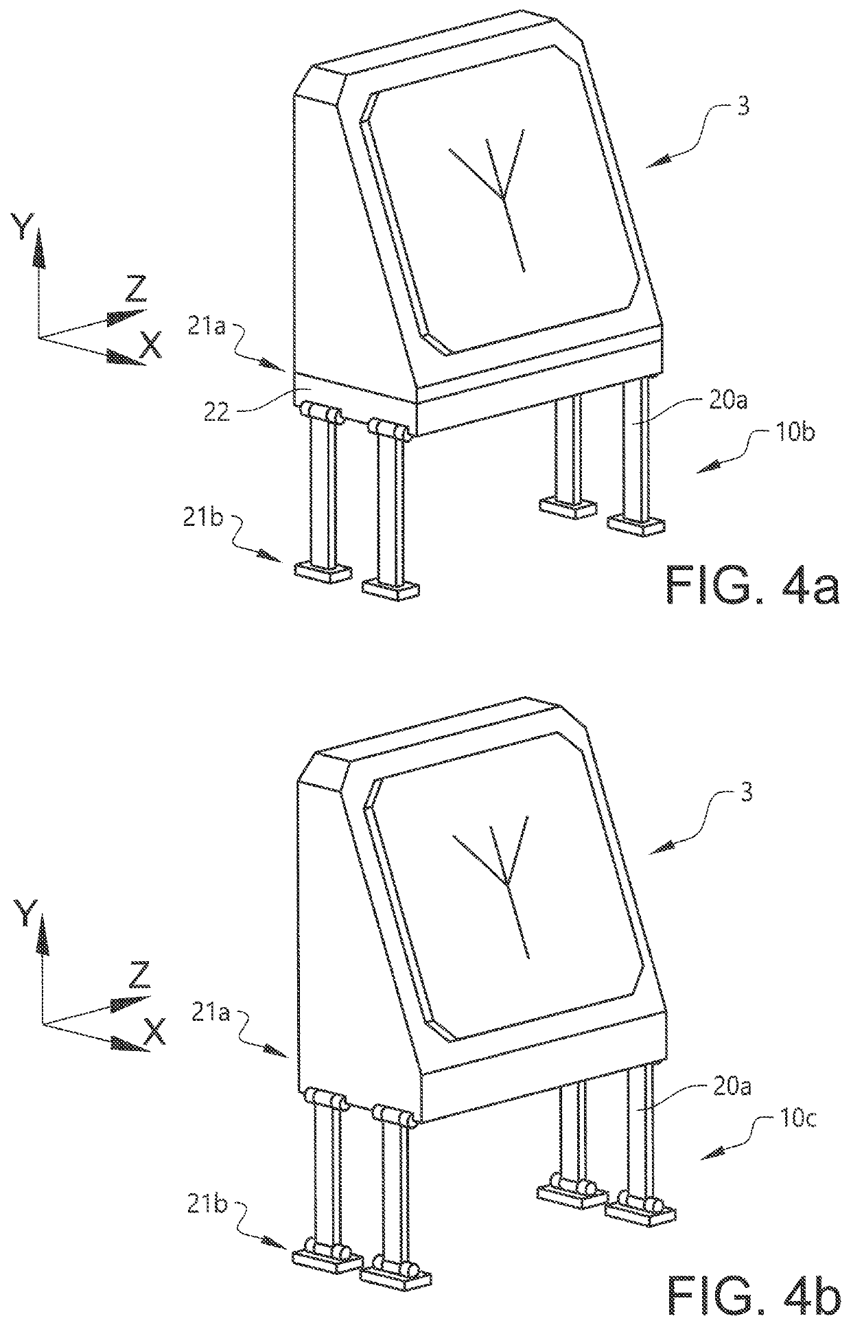
[0029]Once the critical load of a fastener element is exceeded, and the fastener element has started to deform, the load required for further deformation is lower. Thus, dampers configured for dampen compressive movement provide the exemplary advantage that, once the fastener elements of the sensor fastener arrangement starts to deform the reversible deformation by the compressive movement is dampened. Thereby the acceleration the sensor device is exposed to when the fastener elements reversibly deform is decreased.
[0030]Dampers configured for dampening extending movement provide the exemplary advantage that once the fastener elements has been reversibly deformed use of a damper prevents that the deformed fastener element forcefully springs back whereby a whiplash effect can be avoided. Thereby, it may for example be avoided that the fastener element deforms when springing back, or that the sensor device may be damaged due to a whiplash.

Problems solved by technology

Even the smallest spatial dislocation or displacement of the sensor device may deteriorate the measurement data provided by the sensor device and may even make measurement data provided useless.
A small displacement of an aiming device such as a sight may for example give a significant error over distance and a small spatial dislocation of an antenna such as a phased array antenna may provide less useful information, if not compensated for.
Thus, sensor devices, and their installations, are very sensitive to impact force.

Method used


Image

  • Sensor fastener arrangement
  • Sensor fastener arrangement
  • Sensor fastener arrangement

Examples


Embodiment Construction

[0046]The following description of exemplary embodiments of the invention is presented only for purposes of illustration and should not be seen as limiting. The description is not intended to be exhaustive and modifications and variations are possible in the light of the teachings herein, or may be acquired from practice of various alternative embodiments of the invention. The exemplary embodiments discussed herein were chosen and described in order to explain the principles and the nature of various embodiments and its practical application to enable one skilled in the art to utilize the exemplary embodiments in various manners, and with various modifications, as are suited to the particular use contemplated. It should be appreciated that the aspects presented herein separately may be practiced in any combination with each other unless otherwise explicitly is stated.

[0047]FIG. 1 discloses a platform 1, in form of a ship, provided with a sensor device 3, in form of an antenna, arran...


PUM


Abstract

The invention relates to a sensor fastener arrangement (10a-f) for holding a sensor device (3). The sensor fastener arrangement (10a-f) comprises a plurality of fastener elements (20a, 20b). The fastener elements (20a, 20b) are configured to arrange the sensor device (3) to a platform (1). Respective fastener element (20a, 20b) is rigid in a first state and reversibly deformable in a second state. When the platform (1) of the sensor device (10a-f), and / or the sensor device (3), is exposed to an impact force, in turn exposing a fastener element (20a, 20b) to a compressive force exceeding a critical load of that fastener element (20a, 20b), the fastener element (20a, 20b) goes from being in the first state to temporarily being in the second state. Thereby the fastener element (20a, 20b) goes from having a first rigid shape to temporarily being reversibly deformed, after which, when the impact force is terminated, the fastener element (20a, 20b) goes from temporarily being in the second state back to being in the first state. Thereby the fastener element (20a, 20b) goes from temporarily being reversibly deformed to having the first rigid shape.

Description

CROSS REFERENCE TO RELATED APPLICATIONS[0001]This application is a National Stage Application, filed under 35 U.S.C. § 371, of International Application No. PCT / SE2019 / 050821, filed Sep. 3, 2019, which claims priority to Swedish Application No. 1851042-0, filed Sep. 4, 2018; the contents of both of which are hereby incorporated by reference in their entireties.BACKGROUND[0002]Related Field[0003]The invention relates to a sensor fastener arrangement for holding and protecting a sensor device such as an antenna, an aiming device or any other sensor device that requires high pointing accuracy. The invention may be applicable for ships and other naval applications. Although the invention primarily is described with respect to an antenna installation on a ship, the invention is not restricted to this particular use, but may also be used for example for sights or rangefinders, at other naval applications or land vehicles.[0004]Description of Related Art[0005]Reliable and accurate function...

Claims


Application Information

Patent Timeline
Patent Type & Authority Patents(United States)
IPC IPC(8): B63B17/00B63B3/09B63B3/10B63B3/14F16F15/02H01Q1/00H01Q1/20H01Q1/34
CPCB63B17/0081B63B3/09B63B3/10B63B3/14F16F15/02H01Q1/002H01Q1/005H01Q1/20H01Q1/34B63B2017/0054B63G9/00H01Q1/12F16F15/04F16F7/00H01Q1/18
Inventor RYDEN, JANOESTBERG, JOHAN
Owner SAAB AB
Why Eureka
Try Eureka