

Personal electronic device EMP protective enclosure
a protective enclosure and electronic device technology, applied in the direction of emergency protective arrangements for limiting excess voltage/current, electrical equipment, etc., can solve the problems of emp-optimized nuclear devices, low yield, and inoperable devices, so as to reduce radiation leakage paths, enhance display clarity, and prevent moiré patterns
- Summary
- Abstract
- Description
- Claims
- Application Information
AI Technical Summary
Benefits of technology
Problems solved by technology
Method used
Image

Examples
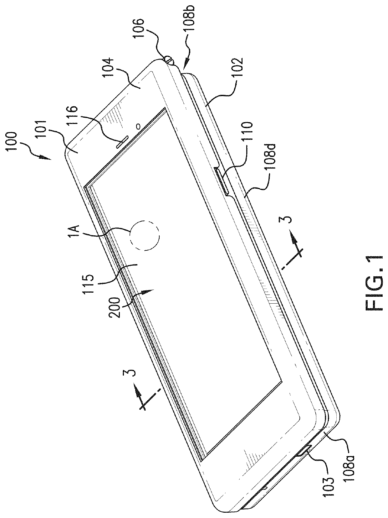
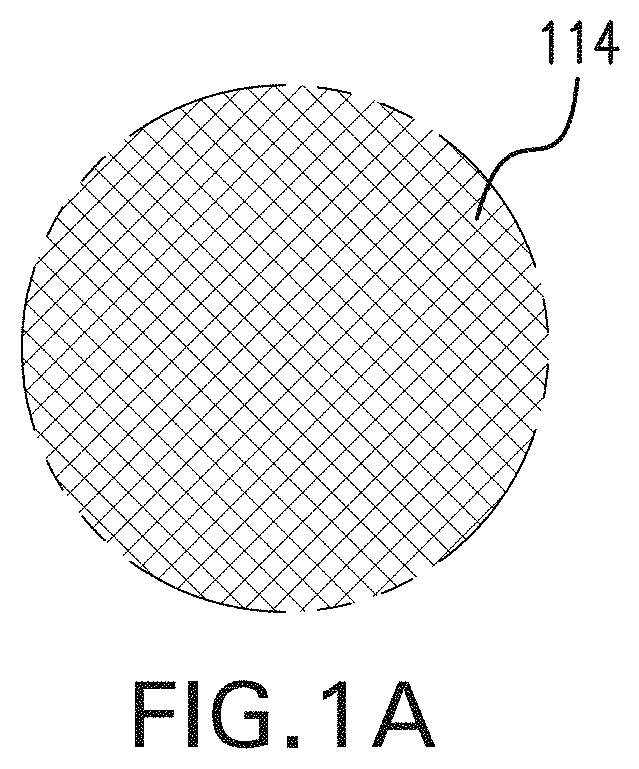
case 100
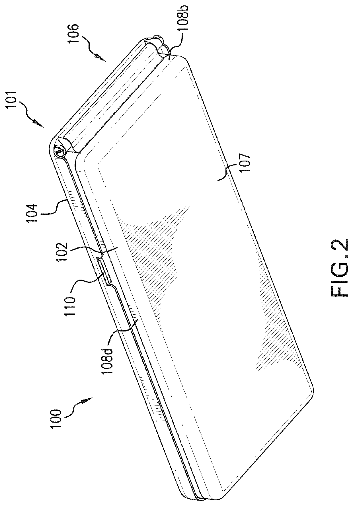
[0028]Case 100 comprises of an enclosure 101 with a hinged “visor” that completely surrounds mobile device 200. This hinged “visor” mechanically and electrically connected to the Faraday cage of enclosure 101 has a portion that aligns with the display where there is a cutout which fully reveals the display of mobile device 200. The cutout contains an optically-transmissive fine wire mesh which provides 80 db of radio attenuation. The mesh is sandwiched between two sheets of transparent plastic for damage and wear protection, with the mesh bonded to the grounded visor frame. Because the standard input entry touchscreen for mobile device 200 is capacitive, it will not function through a grounded mesh screen. Therefore, the user must open the visor to use the touchscreen of mobile device 200. Opening the visor, however, exposes mobile device 200 to EMP damage, requiring the user to take care where and when he opens it. This tradeoff recognizes that most use in emergency conditions is r...
PUM
 Abstract
Description
Claims
Application Information