
Loudspeaker having damper with woven wire and method for manufacturing the same

a technology of woven wire and loudspeaker, which is applied in the field of loudspeakers, can solve the problems of increased fatigue resistance of wire, easy fatigue of wire, and easy to be broken, and achieves the common resonance efficiency of wire damper, improved sound quality of each loudspeaker, and improved manufacturing efficiency.

Active Publication Date: 2022-04-26
CHEN VINCENT
View PDF1 Cites 2 Cited by
  • Summary
  • Abstract
  • Description
  • Claims
  • Application Information

AI Technical Summary

Benefits of technology

The present invention is about a loudspeaker with a damper that uses woven wires and has improved common resonance efficiency, voice coil, and diaphragm. The wires are securely fixed without shifting, resulting in better sound quality consistency. The wire damper is made with uniformly distributed fibers, making it harder, elastic, and tougher to deform or break, leading to improved sound quality. The elastic adjustment areas allow for adjustment of the hardness, elasticity, and toughness of the wire disposing area, ensuring the wire damper is of the same quality across the entire structure. Overall, the present invention provides a loudspeaker with better sound quality and durability.

Problems solved by technology

However, in the conventional loudspeaker, the wire is suspended in the air without any support, so that the wire alone bears the vibration force transmitted from the voice coil.
Thereby, after the voice coil moves rapidly and frequently for a period of time, the wire is easy to fatigue and be broken.
By using the main body of the wire damper to support the wire, the wire has an increased fatigue resistance and becomes not easy to be broken.
The individual problem of the first method for manufacturing wire damper is that: a manual operation of a sewing machine is required to sew and fix the wire on the surface of the base material by the sewing thread.
The individual problems of the second method for manufacturing wire damper are that: first, in the thermoforming process, the position of the wire will shift away from the optimal position, thereby affecting the common resonance efficiency of the wire damper, the voice coil, and the diaphragm; second, the shifting condition of the position of the wire of each wire damper is different from others, such that the sound quality of each loudspeaker is slightly different from others.
First, the steps are complicated.
Then, the wire is harder than the warp yarns and the weft yarns, and the elasticity and toughness of the wire are worse than those of the warp yarns and the weft yarns, such that the wire disposing area is harder than other areas of the wire damper, and the elasticity and toughness of the wire disposing area are worse than those of other areas of the wire damper.
Therefore, the hardness, elasticity, and toughness of the wire damper are non-uniform, resulting in non-uniform elastic resilience and fatigue resistance of the wire damper, which causes the wire damper to be easy to be deformed, thereby affecting the output sound quality of the loudspeaker.
The fine wires of the two common wires are both tightly close to each other, which causes the heat generated by each fine wire to be difficult to dissipate and results in problems of heat accumulation, thereby causing the wires easily to be overheated.

Method used


Image

  • Loudspeaker having damper with woven wire and method for manufacturing the same
  • Loudspeaker having damper with woven wire and method for manufacturing the same
  • Loudspeaker having damper with woven wire and method for manufacturing the same

Examples


Embodiment Construction

[0048]Herein after, a more detailed description of the implementation of the present invention with reference to the drawings and reference symbols, such that those skilled in the art can implement it after studying this written description.

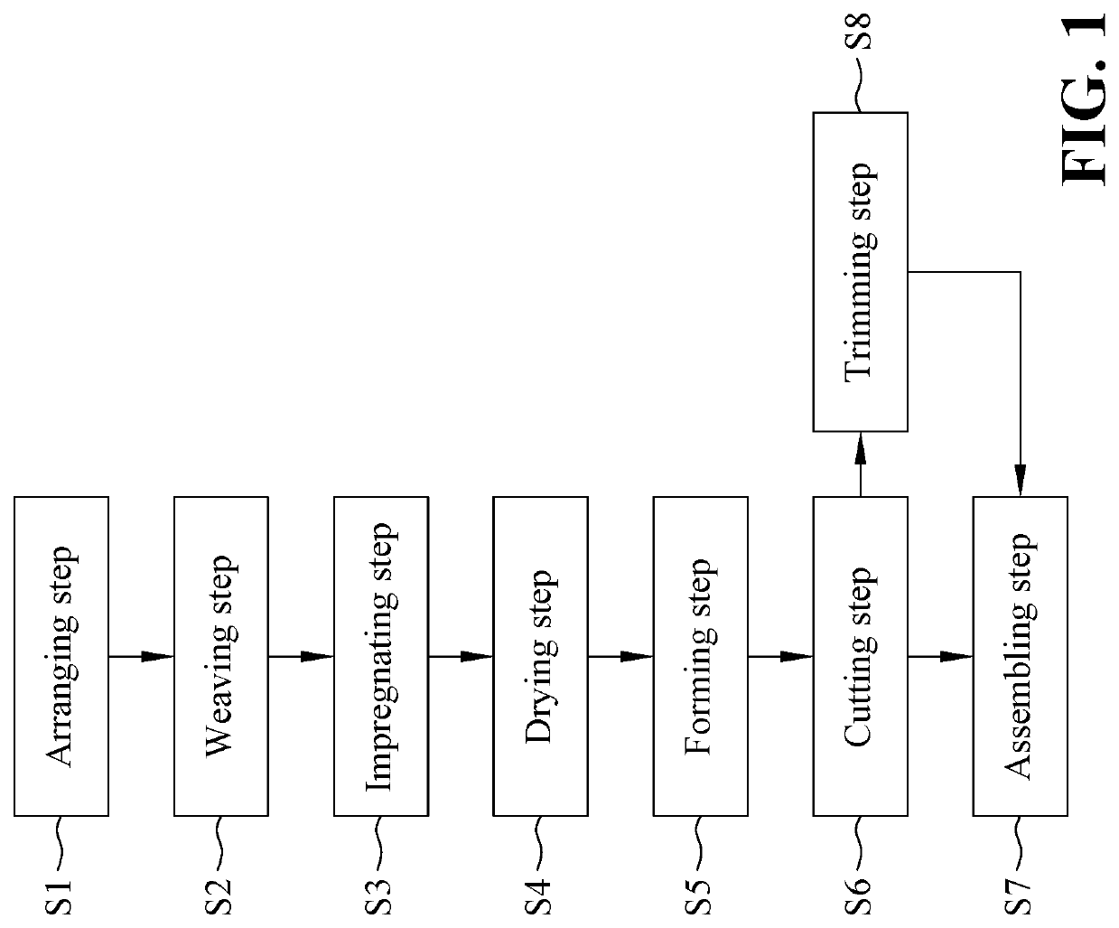
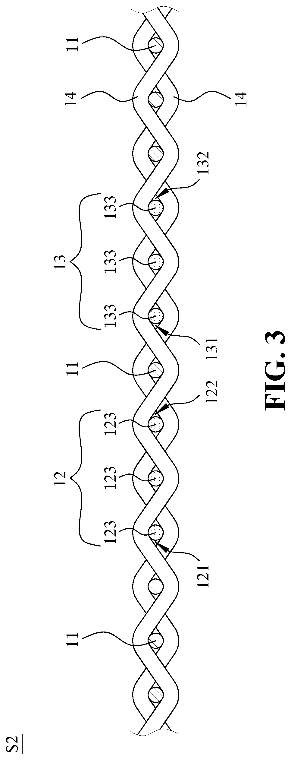
[0049]Referring to FIGS. 1 to 4, the present invention provides a method for manufacturing a loudspeaker having a damper with woven wires, including: an arranging step S1, a weaving step S2, an impregnating step S3, a drying step S4, a forming step S5, a cutting step S6, and an assembling step S7.

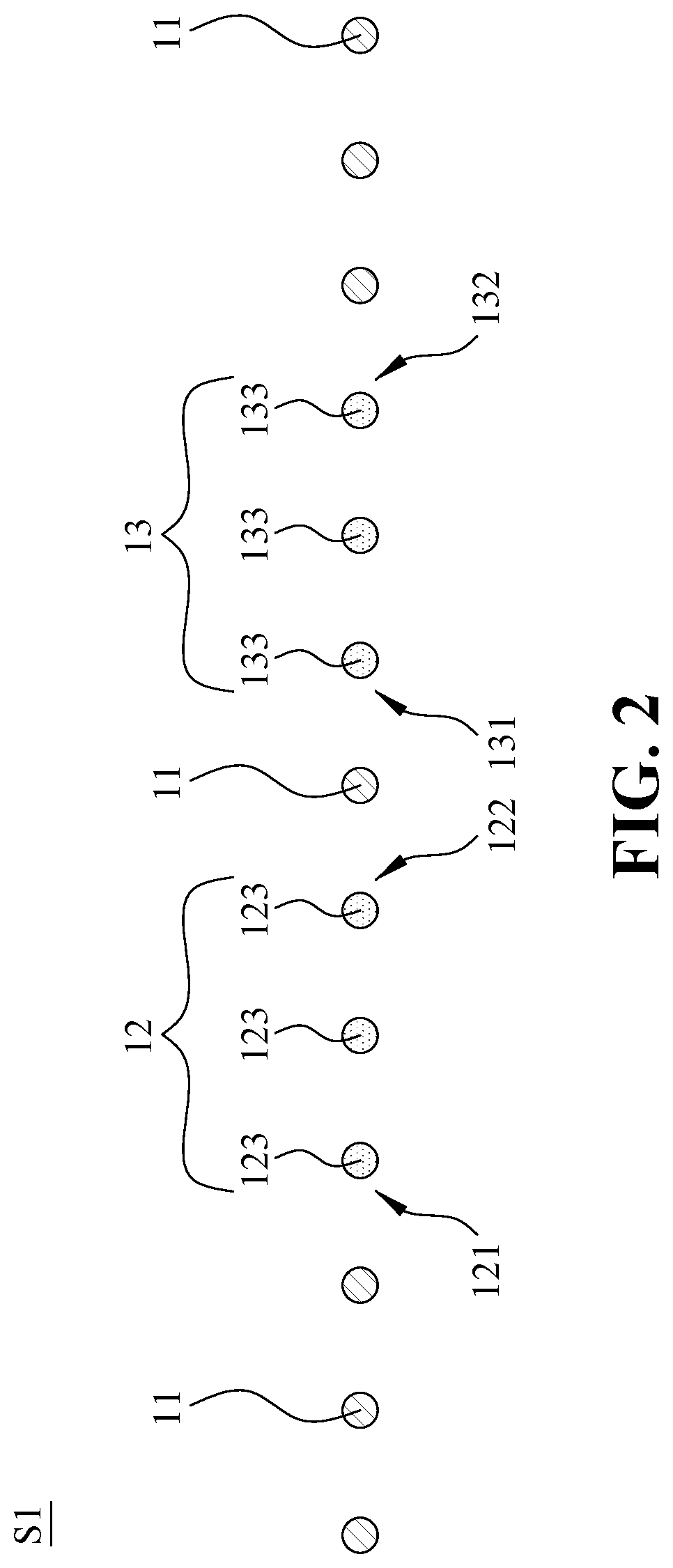
[0050]In the arranging step S1, as shown in FIGS. 1 and 2, a plurality of warp yarns 11, a plurality of first wires 123 and a plurality of second wires 133 are arranged at intervals. The warp yarns 11, the first wires 123 and the second wires 133 extend straight and are parallel to each other. Each first wire 123 and each second wire 133 are both monofilament wires. The first wires 123 are arranged side by side and grouped as a first wire group 12, and b...


PUM

PropertyMeasurementUnit
temperatureaaaaaaaaaa
elastic adjustmentaaaaaaaaaa
widthsaaaaaaaaaa

Abstract

A method for manufacturing a loudspeaker includes arranging, weaving, impregnating, drying, forming, cutting and assembling steps. In the arranging step, warp yarns and wires are arranged at intervals, and the wires are grouped as a wire group. In the weaving step, weft yarns are arranged at intervals and interwoven with the warp yarns and the wires to form a base material by weaving, and an area where the weft yarns are interwoven with the wires is defined as a wire disposing area. In the forming step, a wire damper is formed on the base material by thermoforming; two elastic adjustment areas are formed at the weft yarns between both sides of the wire group and the warp yarns closest to both sides of the wire group; and widths of the elastic adjustment areas are equal to each other and larger than distances between the remaining warp yarns.

Description

BACKGROUND OF THE INVENTION1. Field of the Invention[0001]The present invention relates to a loudspeaker and a method for manufacturing the same, and more particularly, to a loudspeaker having a damper with woven wires and a method for manufacturing the same.2. The Prior Arts[0002]In the general moving coil loudspeaker, the principle that the reaction force of a fixed magnetic field causes another magnetic field to move in the opposite direction (i.e., opposite magnetisms attract each other, and like magnetisms repels each other) is used to produce sound. Further, the power alternating current generated by the power amplifier is transmitted to the voice coil through a wire to change the polarity of the magnetic field, such that the voice coil generates a reaction force against the fixed magnetic region generated by the magnetic circuit device. The forward pulse causes the diaphragm move outward relative to the magnet, while the backward pulse causes the diaphragm move inward. When t...

Claims


Application Information

Patent Timeline
Patent Type & Authority Patents(United States)
IPC IPC(8): H04R31/00D03D1/00D06N3/00H04R9/04
CPCH04R31/003D03D1/00D06N3/0006H04R9/046H04R2307/201D03D15/25D03D13/008D03D13/004H04R9/06H04R9/043H04R31/00H04R9/022H04R1/06
Inventor CHEN, VINCENT
Owner CHEN VINCENT
Learn More