Electronic parts packaging structure and method of manufacturing the same
a technology of electronic parts and packaging structure, applied in the direction of printed circuit manufacturing, printed circuit non-printed electric component association, basic electric elements, etc., can solve the problem of difficult to form desired resist patterns with good precision, and achieve good precision, small depth of focus in exposure, and elimination of variation in bonded height
- Summary
- Abstract
- Description
- Claims
- Application Information
AI Technical Summary
Benefits of technology
Problems solved by technology
Method used
Image
Examples
first embodiment
[0031] (First Embodiment)
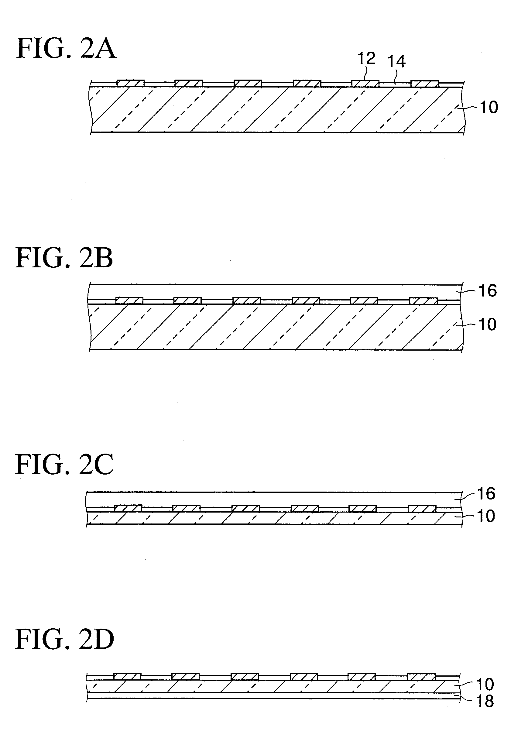
[0032] Next, a method of manufacturing an electronic parts packaging structure according to a first embodiment of the present invention will be explained hereunder. FIG. 2A to FIG. 2N are partial sectional views showing the method of manufacturing the electronic parts packaging structure according to the first embodiment of the present invention.
[0033] As shown in FIG. 2A, first a silicon wafer 10 (semiconductor wafer) on which predetermined transistors, multi-layered wirings (not shown), etc. are formed and which has a thickness of about 400 μm is prepared. Connection terminals 12 made of Al, or the like are exposed from an upper surface of the silicon wafer 10. Portions except the connection terminals 12 are covered with a passivation film 14 made of a silicon nitride film, a polyimide resin, or the like.
[0034] Then, as shown in FIG. 2B, mask member 16 is pasted on a surface of the silicon wafer 10 on the connection terminal 12 side (referred to as an el...
second embodiment
[0074] (Second Embodiment)
[0075]FIG. 3A to FIG. 3K are partial sectional views showing a method of manufacturing an electronic parts packaging structure according to a second embodiment of the present invention. A different point of the second embodiment from the first embodiment reside in that the semiconductor chips are adhered onto the interlayer insulating film not by forming particularly the die attaching member 18 on the back surfaces of the semiconductor chips 11 but by giving the tackiness to the interlayer insulating film on which the semiconductor chips 11 are mounted. In this case, detailed explanation of the same steps as those in the first embodiment will be omitted herein. Also, in FIG. 3A to FIG. 3K, the same reference symbols are affixed to the same elements as those in FIG. 2A to FIG. 2N, and their explanation will be omitted herein.
[0076] In the method of manufacturing the electronic parts packaging structure according to the second embodiment of the present inven...
third embodiment
[0094] (Third Embodiment)
[0095]FIG. 4A to FIG. 4F are partial sectional views showing a method of manufacturing an electronic parts packaging structure according to a third embodiment of the present invention. A different point of the third embodiment from the first embodiment reside in that the die attaching member is not formed on the back surfaces of the semiconductor chips 11 but a tape containing the adhesive material is employed as the dicing tape, and then such adhesive material is transferred onto the back surfaces of the semiconductor chips 11 when the semiconductor chips 11 are picked up from the dicing tape. In this case, detailed explanation of the same steps as those in the first and second embodiments will be omitted herein. Also, in FIG. 4A to FIG. 4F, the same reference symbols are affixed to the same elements as those in FIG. 2A to FIG. 2N and FIG. 3A to FIG. 3K, and their explanation will be omitted herein.
[0096] In the method of manufacturing the electronic parts...
PUM
 Abstract
Description
Claims
Application Information
 - R&D
- Intellectual Property
- Life Sciences
- Materials
- Tech Scout
- Unparalleled Data Quality
- Higher Quality Content
- 60% Fewer Hallucinations
Browse by: Latest US Patents, China's latest patents, Technical Efficacy Thesaurus, Application Domain, Technology Topic, Popular Technical Reports.
© 2025 PatSnap. All rights reserved.Legal|Privacy policy|Modern Slavery Act Transparency Statement|Sitemap|About US| Contact US: help@patsnap.com


