
Intraventricular pulsating blood pump

a blood pump and pulsating technology, applied in the field of ventricular assist devices, can solve the problems of negative effects on the valve, suction and thrombosis, long time-consuming and laborious closure of the artery flap, etc., and achieve the effect of reducing the possibility of hemolysis and thrombosis

Active Publication Date: 2022-05-10
MAGASSIST CO LTD
View PDF16 Cites 2 Cited by
  • Summary
  • Abstract
  • Description
  • Claims
  • Application Information

AI Technical Summary

Benefits of technology

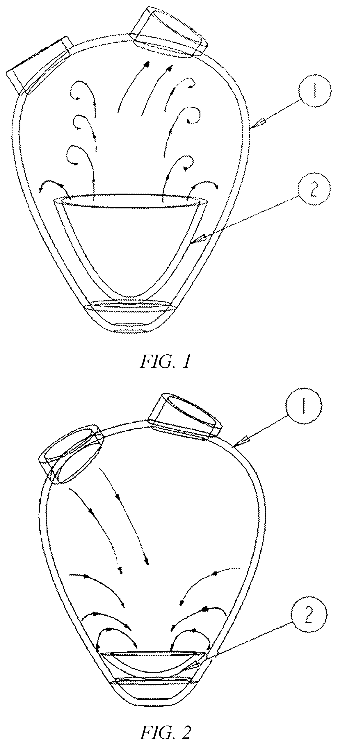
[0014]Preferably, the contraction and relaxation of the bell-shaped pump body allows the blood to produce the Venturi effect, thereby producing a convoluted blood flow field.
[0024]1. all blood enters the cardiovascular system through the original passage (atrioventricular valve-ventricle-aortic valve-arteries), and a good intraventricular pressure distribution is formed to create a scouring blood flow field, avoiding thrombus caused by flow field dead zone;
[0026]3. the actuator made of a flexible material can greatly reduce the continuous non-physiological shear stress to the blood when the blood pump is working, reducing the possibility of hemolysis and thrombosis.

Problems solved by technology

1. the inlet of the ventricular assist device in prior art forms an uneven pressure distribution in the ventricle, which easily causes negative effects in the ventricle, including suction and thrombus;
2. the ventricular assist device in prior art changes the original blood flow mode, resulting in closure of the artery flap for a long time, which has a negative impact on the valve (valvular incompetence, sclerosis, sticky, etc.);
3. the ventricular assist device in prior art is a rotary continuous blood flow pump whose action produces continuous shear force to the blood, leading to hemolysis and blood-related complications. The blade made of rigid material (such as metal) produces large and continuous shear stress to the blood during the high speed rotary motion, resulting in damage to blood cells, and thus resulting in hemolysis and thrombus, and resulting in postoperative sequelae to the patients implanted with blood pumps such as stroke;
4. since the blood pumping process takes place in a closed shell-like structure, the flow field dead zone usually occurs due to the mechanical structure design, causing the blood in some dead zones to be stagnant for a long time, which leads to coagulation.
The above-mentioned problem of flow field dead zone not only occurs in the blood pumps with blades, but also in the above-mentioned U.S. patent, which uses a flexible material as an actuator, since it adopts a closed-heart-assisted technology, it also causes a problem of flow field dead zone.
Some other pulsating blood pump cannot avoid the problem of blood compatibility at the joint of the valve switch because of the use of the artificial valve mechanism.
The clinical results show that the blood compatibility is even worse than that of the blood pumps with blades.

Method used


Image

  • Intraventricular pulsating blood pump
  • Intraventricular pulsating blood pump

Examples


embodiment 1

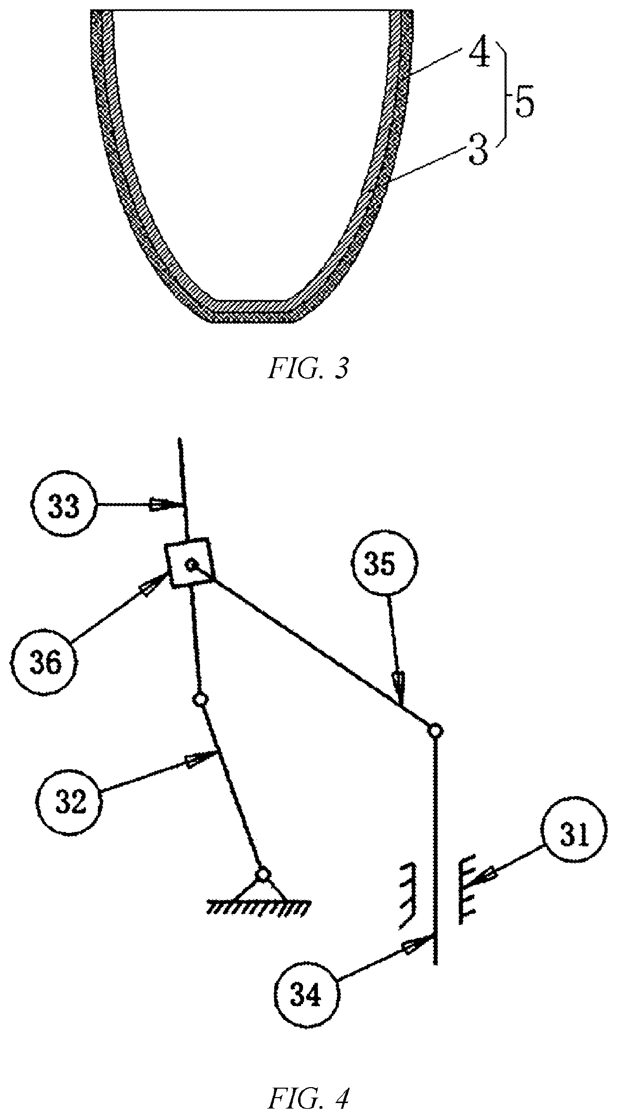
[0033]Referring to FIG. 1 to FIG. 4, an intraventricular pulsating blood pump is shown, the pulsating blood pump 2 is fixedly disposed at the ventricularapex inside the ventricle 1 and is generally jellyfish-shaped. The pulsating blood pump 2 includes a skeleton 3, an elastic film 4 and a driving source, the elastic film 4 covers on the outer side of the skeleton 3 to form a bell-shaped pump body 5, the outlet of the bell-shaped pump body 5 faces to the outlet of the ventricle 1. The driving source is coupled to the skeleton 3 to drive the bell-shaped pump body 5 to contract or relax, the contraction or relaxation of the bell-shaped pump body 5 drives the blood in the ventricle 1 to eject directionally to the artery, and forms a convoluted blood flow field between the inner wall of the bell-shaped pump body 5 and the inner wall of the ventricle 1.

[0034]Inspired by the principle of jellyfish swimming, the invention provides a non-rotatory bionic intraventricular pulsating blood pump....

embodiment 2

[0041]The intraventricular pulsating blood pump of Embodiment 2 is different from that of Embodiment 1 in that, the skeleton or the film is made of a dielectric elastomer material, the driving source is an electric field, and the dielectric elastomer material generates a large driving force and elastic deformation under the electric field to achieve contraction and relaxation.

embodiment 3

[0042]The intraventricular pulsating blood pump of Embodiment 3 is different from that of Embodiment 1 in that, the driving source is an air cylinder.


PUM


Abstract

The invention provides an intraventricular pulsating blood pump fixedly disposed at the ventricularapex inside the ventricle to generate pulsation action. The pulsating blood pump is substantially jellyfish-shaped and includes a bell-shaped pump body and a driving source, an opening of the bell-shaped pump body faces to the outlet of the ventricle, the driving source drives the bell-shaped pump body to contract or relax, and the contraction or relaxation of the bell-shaped pump body drives the blood in the ventricle to eject directionally to the artery and form a convoluted blood flow field between the inner wall of the bell-shaped pump body and the inner wall of the ventricle. The invention not only provides assist to ventricular by pulsating blood flow, but also optimizes the flow field and pressure distribution in the ventricle, the blood pump of the invention is better in biocompatibility than the blood pumps in prior art.

Description

[0001]This application is the National Stage Application PCT / CN2016 / 102856, filed on Oct. 21, 2016, which claims priority to Chinese Patent Application No.: 201610891191.4, filed on Oct. 13, 2016, which is incorporated by reference for all purposes as if fully set forth herein.TECHNICAL FIELD[0002]The invention relates to the field of ventricular assist devices, and more particularly to an intraventricular pulsating blood pump.BACKGROUND[0003]The ventricular assist device (blood pump) is a mechanical circulation assist device made of artificial materials to assist heart pumping of patients with end-stage heart failure. This type of device has been clinically applied in occident and successfully saved or continued the lives of a large number of patients with heart disease.[0004]At present, most of the blood pumps in the world that have been put into clinical application or are in the research and development stage are based on the basic principle of rotary turbomachinery, with the ro...

Claims


Application Information

Patent Timeline
Patent Type & Authority Patents(United States)
IPC IPC(8): A61M60/40A61M60/148A61M60/268
CPCA61M60/148A61M60/268A61M60/40A61M2206/10A61M2210/125A61M60/274A61M60/17A61M60/837A61M60/443
Inventor XU, BOLINGDANG, WEIGUOHUANG, PENGHUI
Owner MAGASSIST CO LTD
Learn More