Method and apparatus for removing NOx and N2O from a gas

a technology of nox and n2o, which is applied in the direction of physical/chemical process catalysts, metal/metal-oxide/metal-hydroxide catalysts, separation processes, etc., can solve the problems of unsatisfactory ammonia slip, environmental impact and may generate an additional cost, and the target concentration of nox may not be reached, so as to achieve easy control of ammonia flow and improve accuracy. , the effect of improving the accuracy

Active Publication Date: 2022-05-10
CASALE SA
View PDF38 Cites 0 Cited by
  • Summary
  • Abstract
  • Description
  • Claims
  • Application Information

AI Technical Summary

Benefits of technology

[0024]Accordingly, the great advantage of the invention is the system being able to reduce or eliminate the risk of excursion out of the limit and being able to operate under more stringent regulation. For example, the invention may obtain a final concentration of: less than 25 ppm of NOx, less than 30 ppm of N2O, less than 2 ppm of ammonia.
[0025]The three catalytic beds may have any suitable catalyst. Particularly, the two de-NOx catalytic beds may have the same or a different catalyst. According to preferred embodiments, the catalyst of the first bed (first de-NOx) is copper exchanged zeolite; the catalyst of the second bed (de-N2O) is iron exchanged zeolite; the catalyst of the third bed (second de-NOx) is Vanadium oxide. In some embodiments, also an iron-based catalyst may be used for the first and / or the second de-NOx catalytic bed.
[0026]In a preferred embodiment the second de-NOx catalytic bed comprises a catalyst which is iron exchanged zeolite and the gas admitted into said second catalytic bed has a molar ratio of NH3 / NOx greater than 1.33. Said molar ratio NH3 / NOx is understood as molar ratio of ammonia to the sum of NO and NO2. Even more preferably said ratio is greater than 1.4. A more preferred ratio is in the range 1.4 to 1.6. More preferably said ratio is 1.5 or about 1.5. Still more preferably, said iron exchanged zeolite catalyst of the second catalytic bed operates at a temperature around 430° C.
[0027]In a preferred embodiment, both the first and second de-NOx catalytic beds comprise iron exchanged zeolite catalyst. More preferably, the first catalytic bed operates with NH3 / NOx less than 1 to keep some NOx in the gas for subsequent removal of N2O.
[0028]The applicant has found that the above conditions of de-NOx bed result in a virtually absent ammonia slip, typically less than 1 ppm. Also, a removal of almost all N2O (greater than 99%) is reached. Accordingly the invention allows meet the most stringent limits of NH3 and NOx.
[0029]According to some embodiments, an apparatus for reducing the content of NOx and N2O in a gas, comprises at least: a first de-NOx catalytic bed and a device arranged to introduce a first amount of a NOx reducing agent in the input gas, so that the input gas is treated in the first de-NOx bed with the first amount of reducing agent; a de-N2O catalytic bed arranged to treat the effluent of said first de-NOx catalytic bed to remove N2O, and a second de-NOx catalytic bed and a device arranged to introduce a second amount of a NOx reducing agent in the gas effluent from said de-N2O catalytic bed, so that said effluent is treated in the second de-NOx bed with the second amount of reducing agent.

Problems solved by technology

This technique, however, requires a very accurate regulation of the added ammonia and intensive mixing between ammonia and the gas, otherwise the target concentration of NOx may not be reached or some ammonia may escape the second bed (ammonia slip).
A fluctuation of the process may cause the release of NOx and / or ammonia outside the limit, which causes an environmental impact and may generate an additional cost.
For example, some countries prescribe that the release of ammonia into atmosphere is subject to a penalty fee, making ammonia slip undesirable.
A further reason why ammonia slip is undesirable is the possible formation of ammonium nitrite or nitrate which can lead to damage of equipment, for example of a downstream expander.
Typically, the flowrate of ammonia must be regulated with accuracy of 1-2% which is difficult to obtain.
The above problem is more challenging as the requirement in terms of emissions of NOx and ammonia become more stringent in several countries.

Method used


Image

  • Method and apparatus for removing NOx and N2O from a gas
  • Method and apparatus for removing NOx and N2O from a gas

Examples


example

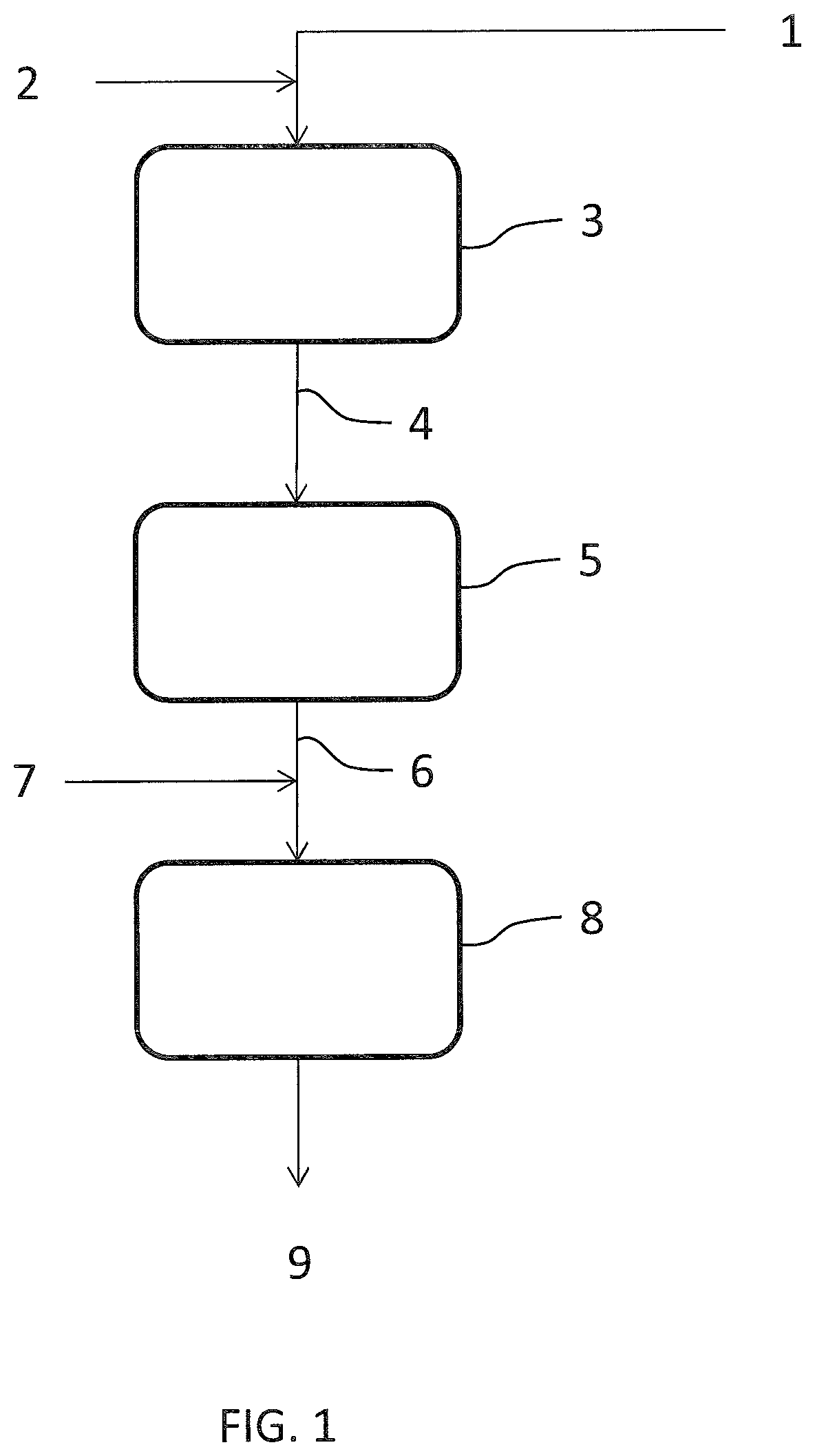
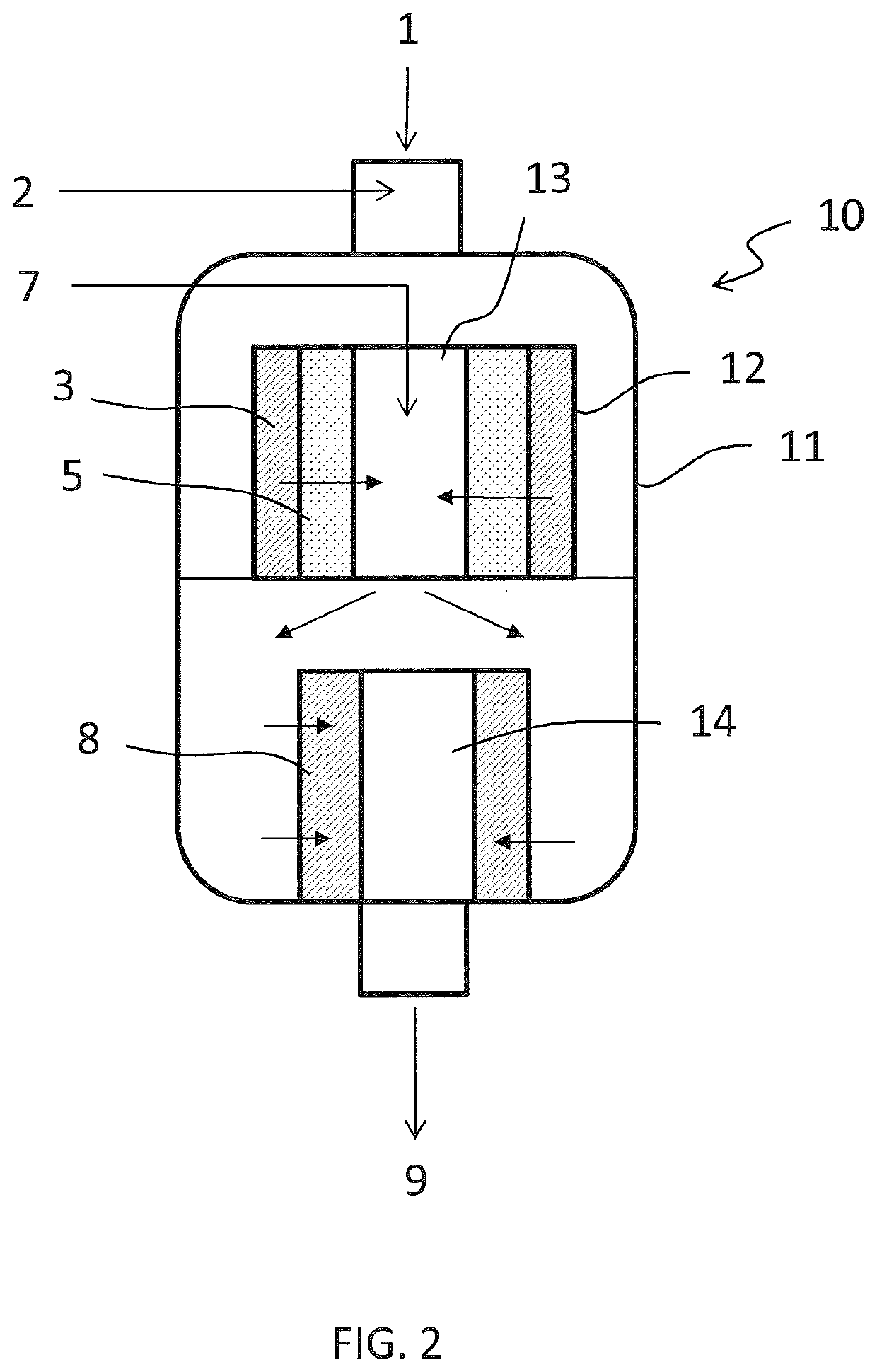
[0049]An off gas 1 from synthesis of nitrous acid has a flowrate of 4100 kmol / h and contains 700 ppm of NOx (NO+NO2) and 900 ppm of N2O. The gas 1 further contains 3% of oxygen.

[0050]The first de-NOx catalytic bed 3 has a copper exchanged zeolite catalyst and a space velocity of 15000 h−1. Ammonia 2 is added in an amount corresponding to 560 ppm in the gas 1. After a passage over said bed 3, the effluent gas stream 4 contains 145 ppm of NOx and 950 ppm of N2O.

[0051]The de-N2O catalytic bed 5 has an iron exchanged zeolite catalyst and has a space velocity of 5000 h−1. After a passage over said de-N2O bed 5, the effluent gas 6 still contains 145 ppm of NOx but only 20 ppm of N2O.

[0052]Said gas 6 is added with ammonia 7 and passed over the second de-NOx catalytic bed 8. The set point of the flowrate of ammonia 7 corresponds to 140 ppm in the gas, being a function of the NOx still contained in the gas.

[0053]The second de-NOx catalytic bed 8 preferably has a vanadium oxide catalyst and a...


PUM

PropertyMeasurementUnit
molar ratioaaaaaaaaaa
temperatureaaaaaaaaaa

Abstract

Method for reducing the content of nitrogen oxides NOx and nitrous oxide N2O in an input gas, comprising the steps of: treating said gas with a first amount of a NOx reducing agent in a first de-NOx catalytic bed; treating the effluent of said first de-NOx catalytic bed in at least one de-N2O catalytic bed for removal of N2O; treating the effluent of said at least one de-N2O catalytic bed with a second amount of a NOx reducing agent in a second de-NOx catalytic bed.

Description

[0001]This application is a national phase of PCT / EP2016 / 076152, filed Oct. 28, 2016, and claims priority to EP 15191816.6, filed Oct. 28, 2015, the entire contents of both of which are hereby incorporated by reference.FIELD OF THE INVENTION[0002]The invention relates to systems for reducing the NOx and N2O content of a gas.Prior Art[0003]Many industrial processes discharge a gas containing nitrogen oxides (NOx) and nitrous oxide (N2O). In particular, any combustion process produces exhaust gases containing NOx and N2O. Another significant case is given by industrial production of nitric acid, which releases an offgas mainly consisting of nitrogen, Oxygen and unconverted NOx and N2O. The term nitrogen oxides or NOx collectively denotes nitrogen monoxide (NO) and dioxide (NO2).[0004]NOx and N2O are known pollutants and the related emissions are subject to strict regulations. Hence a treatment of said combustion gas or offgas in a suitable de-NOx system is indispensable.[0005]A prior ...

Claims


Application Information

Patent Timeline
Patent Type & Authority Patents(United States)
IPC IPC(8): B01D53/86B01J23/22B01J29/072
CPCB01D53/8628B01D53/869B01D53/8631B01D53/8696B01J23/22B01J29/072B01D2251/2062B01D2255/20723B01D2255/20738B01D2255/20761B01D2255/50B01D2257/402B01D2257/404Y02C20/10B01D53/86
Inventor GRANGER, JEAN FRANÇOIS
Owner CASALE SA
Why Eureka
Try Eureka