Zoom lens and imaging apparatus
- Summary
- Abstract
- Description
- Claims
- Application Information
AI Technical Summary
Benefits of technology
Problems solved by technology
Method used
Image

Examples
example 1
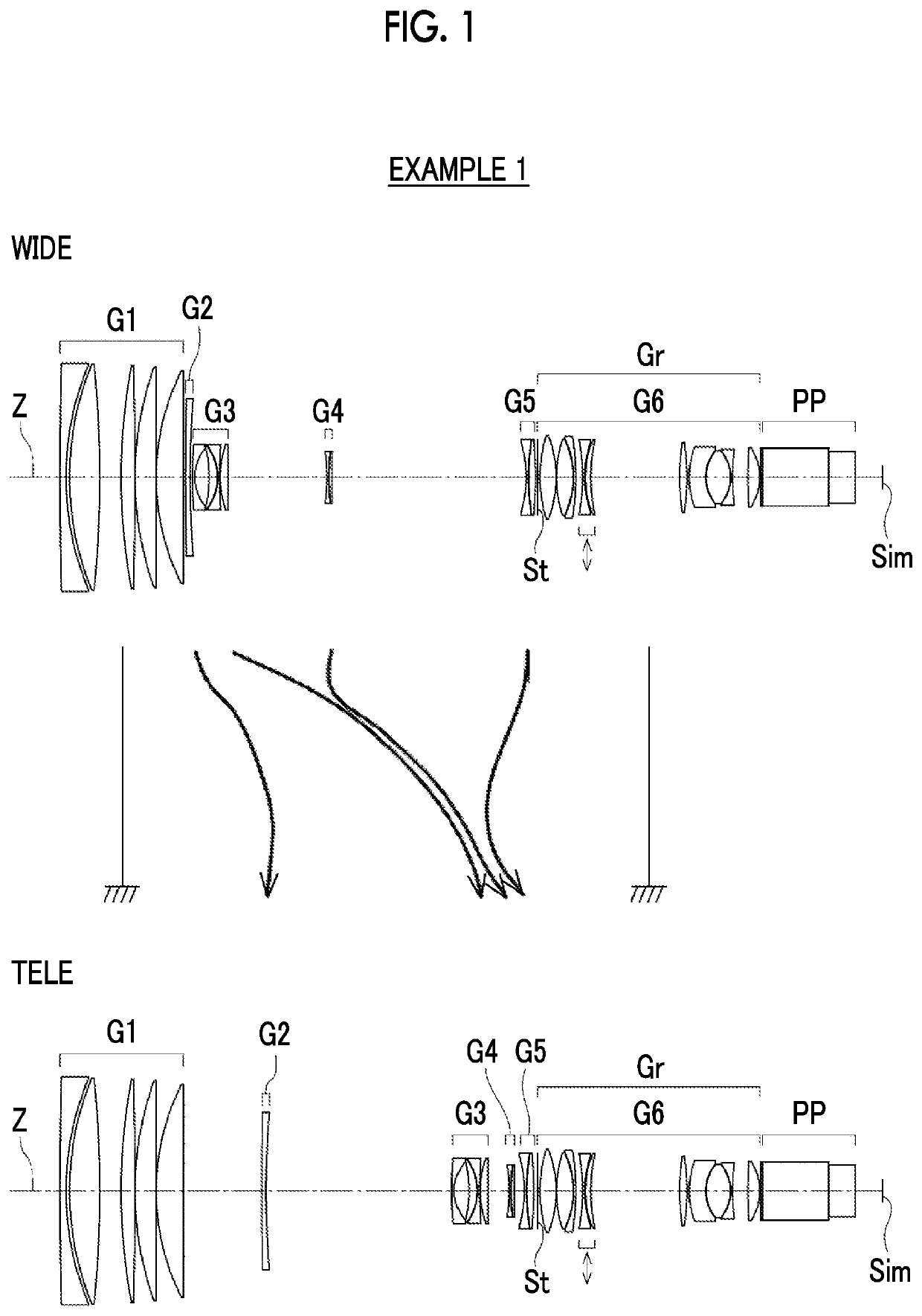
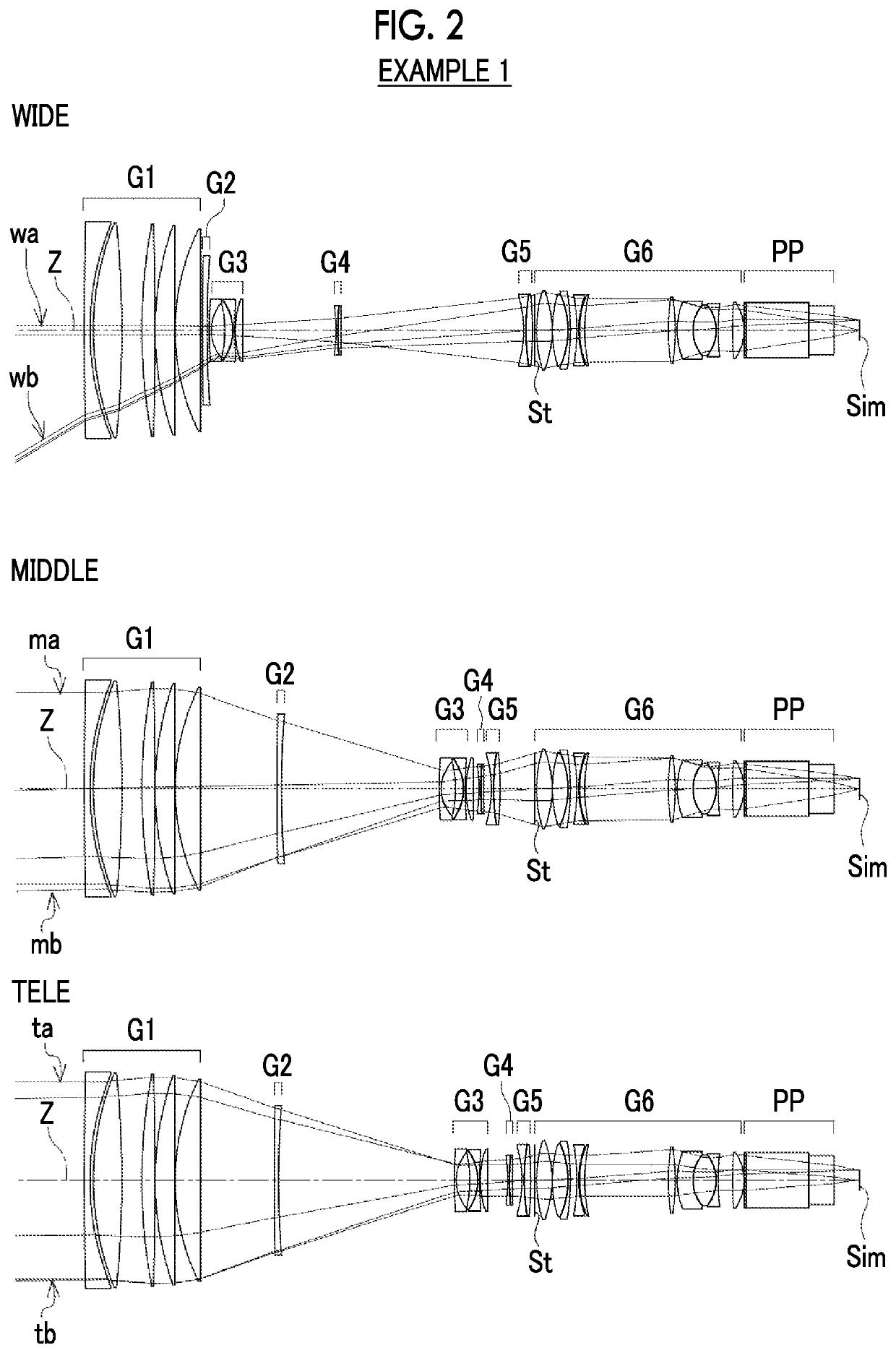
[0084]FIG. 1 is a cross-sectional view of a zoom lens of Example 1, and an illustration method and a configuration thereof is as described above. Therefore, repeated description is partially omitted herein. The zoom lens of Example 1 consists of, in order from the object side to the image side, a first lens group G1 having a positive refractive power; a second lens group G2 having a negative refractive power; a third lens group G3 having a negative refractive power; a fourth lens group G4 having a negative refractive power; a fifth lens group G5 having a negative refractive power; and a sixth lens group G6 having a positive refractive power. The sixth lens group G6 corresponds to the rear group Gr. During zooming, the first lens group G1 and the sixth lens group G6 remain with respect to the image plane Sim, and the second lens group G2, the third lens group G3, the fourth lens group G4, and the fifth lens group G5 move in the optical axis direction by changing the distance between ...
example 2
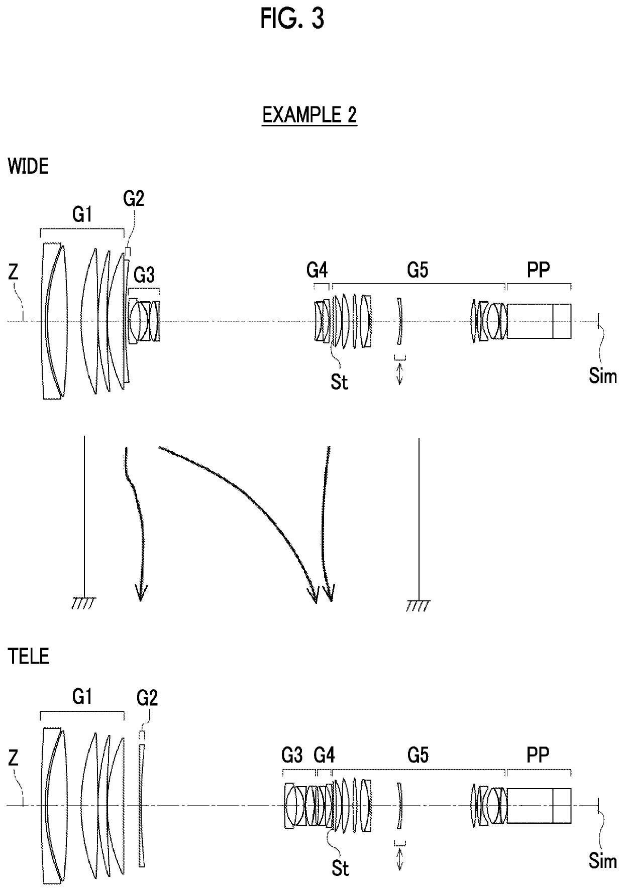
[0100]FIG. 3 is a cross-sectional view illustrating a configuration of the zoom lens of Example 2. The zoom lens of Example 2 consists of, in order from the object side to the image side, a first lens group G1 having a positive refractive power; a second lens group G2 having a negative refractive power; a third lens group G3 having a negative refractive power; a fourth lens group G4 having a negative refractive power; and a fifth lens group G5 having a positive refractive power. The fifth lens group G5 corresponds to the rear group Gr. During zooming, the first lens group G1 and the fifth lens group G5 remain with respect to the image plane Sim, and the second lens group G2, the third lens group G3, and the fourth lens group G4 move in the direction of the optical axis by changing the distance between lens groups adjacent to each other. The vibration reduction group consists of a sixth lens from the object side of the fifth lens group G5.
[0101]Tables 4A and 4B show basic lens data o...
example 3
[0105]FIG. 4 is a cross-sectional view illustrating a configuration of the zoom lens of Example 3. The zoom lens of Example 3 consists of, in order from the object side to the image side, a first lens group G1 having a positive refractive power; a second lens group G2 having a negative refractive power; a third lens group G3 having a negative refractive power; a fourth lens group G4 having a negative refractive power; a fifth lens group G5 having a negative refractive power; and a sixth lens group G6 having a positive refractive power. The sixth lens group G6 corresponds to the rear group Gr. During zooming, the first lens group G1 and the sixth lens group G6 remain with respect to the image plane Sim, and the second lens group G2, the third lens group G3, the fourth lens group G4, and the fifth lens group G5 move in the optical axis direction by changing the distance between lens groups adjacent to each other. The vibration reduction group consists of a sixth lens and a seventh len...
PUM
 Abstract
Description
Claims
Application Information
 - R&D Engineer
- R&D Manager
- IP Professional
- Industry Leading Data Capabilities
- Powerful AI technology
- Patent DNA Extraction
Browse by: Latest US Patents, China's latest patents, Technical Efficacy Thesaurus, Application Domain, Technology Topic.
© 2024 PatSnap. All rights reserved.Legal|Privacy policy|Modern Slavery Act Transparency Statement|Sitemap