Method of and apparatus for monitoring positions on an object

a technology for monitoring positions and objects, applied in the direction of measuring devices, instruments, using optical means, etc., can solve problems such as interference with system operation, false positive detection, and noisy measurements

Active Publication Date: 2022-05-31
FNV IP BV
View PDF27 Cites 0 Cited by
  • Summary
  • Abstract
  • Description
  • Claims
  • Application Information

AI Technical Summary

Benefits of technology

[0008]More specifically, it is the objective of the present invention to overcome the shortcomings of the prior art to allow sensing directional data from beacons in bright ambient light. It is a further objective of the present invention to provide a method to suppress the signal created in the image sensor, caused by spurious light from the environment.
[0020]In an alternative embodiment, the light emitting part of the beacons can be formed by the end of an optical waveguide, such as optical fibres. Such embodiments allow the beacons to be very small while the light source can be remote, thereby allowing beacons to be accommodated in limited spaces.
[0024]In alternative embodiments of the invention, the beacons may be provided with a communication unit such as a light communication unit or a networking device. In such embodiments the controller of the beacons can be re-programmed. Further, a beacon can also be activated or deactivated remotely. Such embodiments allow the controlling of a beacon without the necessity of physical access to the location at which the beacon is mounted.

Problems solved by technology

Higher levels of ambient light could interfere with the functioning of the system.
The use of a moving camera imposes limitations on the signal processing resulting in noisy measurements and the possibility of detecting “ghost” beacons (false positives).
Moreover, this document has no way of identifying the attitude (pitch / roll) of the LED beacons.
Moreover, this document describes a simple time delay method to identify different beacons but that does not allow telemetry of other information.
However, the document does not describe a system to calculate ray angles to the beacons and is thus by nature less accurate.

Method used


Image

  • Method of and apparatus for monitoring positions on an object
  • Method of and apparatus for monitoring positions on an object
  • Method of and apparatus for monitoring positions on an object

Examples


Embodiment Construction

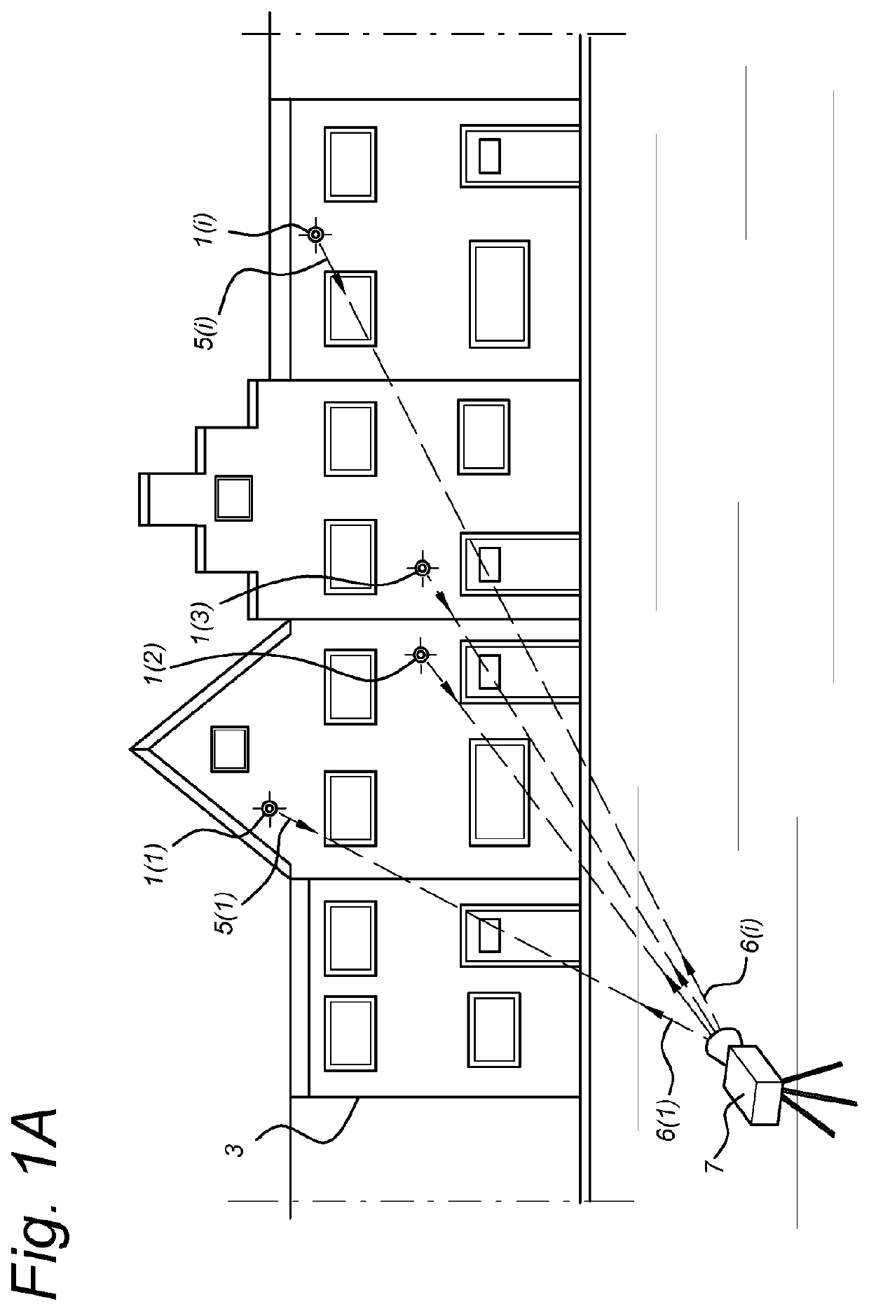
[0041]The present invention tracks movement of objects by tracking one or more light sources (“beacons”) attached to the object. The beacons are, preferably, discerned from other light sources by using correlation techniques. For this means it is important the beacon has a predetermined light pattern. This will be explained in detail below.

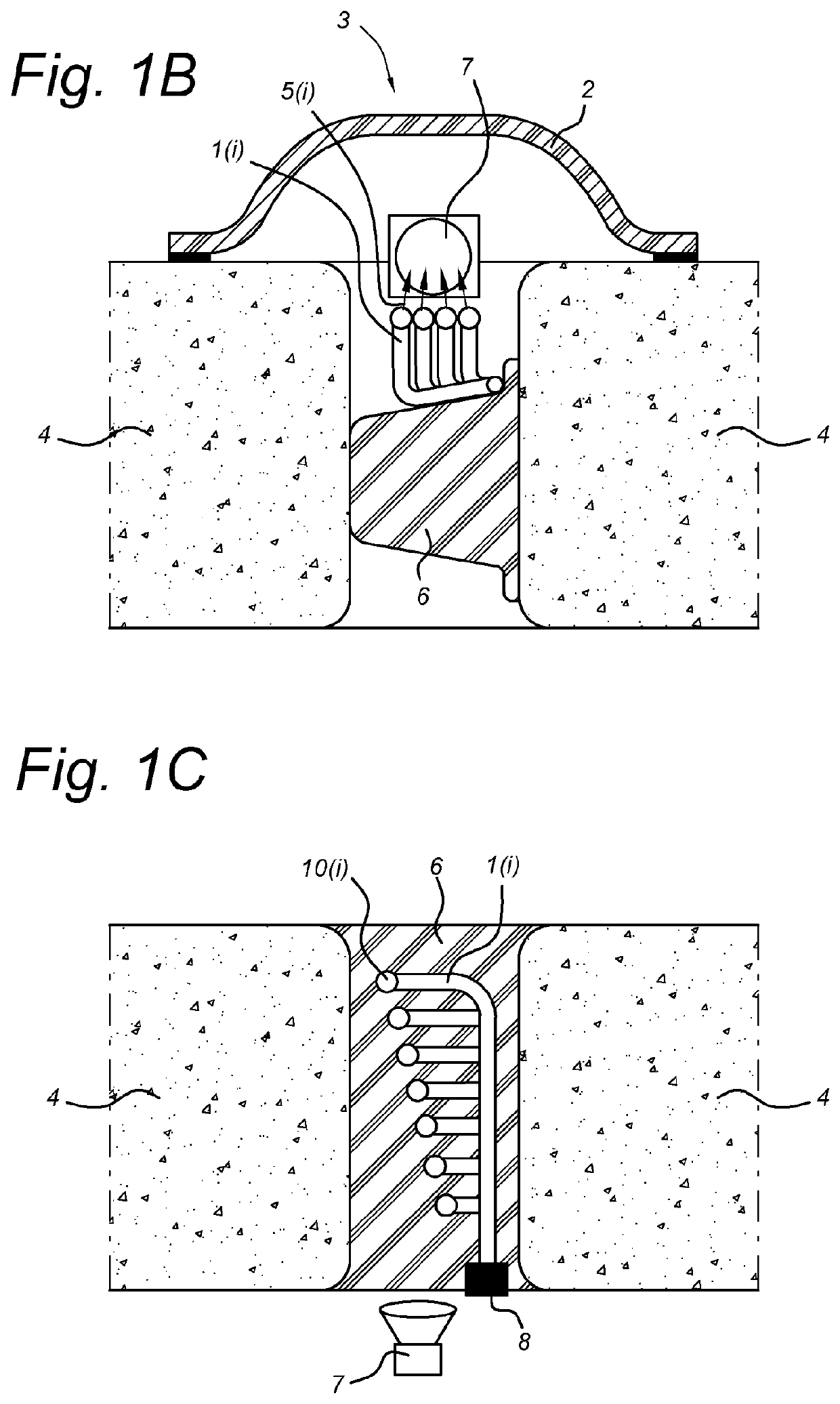
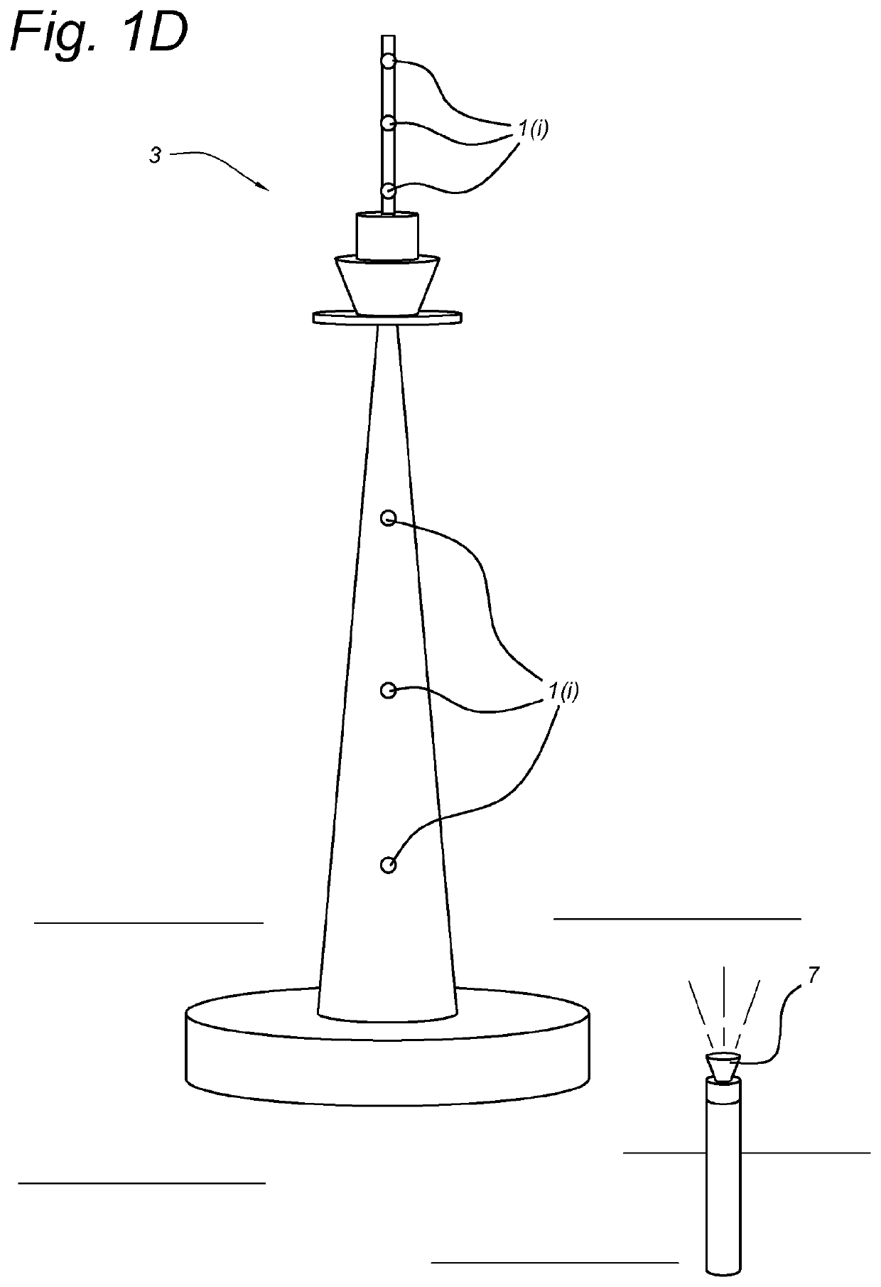
[0042]FIG. 1a shows a possible setup of a system in which an object 3 is monitored. The system comprises an apparatus, like a camera 7. The system also comprises one or more beacons 1(i), i=1, 2, 3, . . . , I which are attached to object 3. The object 3 is shown as comprising one or more buildings to which the beacons 1(i) are fixed. However, the object 3 may alternatively be any other construction like a tunnel (FIGS. 1b, 1c and 1e), a tower (FIG. 1d), a bridge (FIG. 1f), but also a vehicle (like a boat on land), etc. However, object 3 may also be a natural object like a big rock.

[0043]One camera 7 is shown. However, the system may comprise more ...


PUM


Abstract

An apparatus monitors positions on an external object having at least one beacon (1(i), i=1, 2, . . . , I) attached to it. The apparatus has an image sensor (11), a lens system (13) and a processing unit (9). The lens system (13) receives at least one light beam (5(i)) transmitted from the at least one beacon (1(i)) and transfer the at least one light beam (5(i)) to the image sensor (11). The image sensor (11) forms image data. The processing unit (9) identifies the at least one beacon (1(i)) within the image data based on the at least one light beam (5(i)), determines current location data of the at least one beacon (1(i)) based on the image data, compares the current location data with former location data of the one or more beacons (1(i)) as stored in a memory (15) and determines whether the object has moved relative to a fixed reference frame based on the comparison.

Description

CROSS-REFERENCE TO RELATED APPLICATIONS[0001]This application is a national stage application of International Application No. PCT / NL2019 / 050035, which was filed on Jan. 22, 2019, which claims priority to Netherlands Application Number 2020304 filed on Jan. 22, 2018, of which is incorporated by reference in its entirety.FIELD OF THE INVENTION[0002]The present invention relates to a method of and apparatus for monitoring positions on an object.BACKGROUND ART[0003]Such a system is known from patent document WO 2016 / 068715 A1 disclosing an underwater positioning system providing positioning information for a rover, moveable within a reference frame. Such a system may comprise at least one beacon having a light source located at a fixed position within the reference frame, an underwater imaging device mounted to a rover in order to observe the beacon's light source from different viewpoints for the determining of direction data representing a direction or change thereof of the beacon's ...

Claims


Application Information

Patent Timeline
Patent Type & Authority Patents(United States)
IPC IPC(8): G01B11/16G01B11/00
CPCG01B11/16G01B11/002
Inventor VAN WEEREN, DENNISJONGSMA, AMOUD MARCSEIBERT, JOACHIM ULRICH
Owner FNV IP BV
Why Eureka
Try Eureka