Method to generate magnetic resonance measurement data with image contrast selected and produced by preparation pulses

a technology of image contrast and magnetic resonance measurement, which is applied in the direction of geological measurements, reradiation, sensors, etc., can solve the problem that the desired contrast is no longer guaranteed, and achieve the effect of reducing the total measurement time to scan the k-space corresponding to the examination region, reducing the specific absorption rate, and reducing the exposure to the examination subj

Active Publication Date: 2013-04-04
SIEMENS HEALTHCARE GMBH
View PDF4 Cites 1 Cited by
  • Summary
  • Abstract
  • Description
  • Claims
  • Application Information

AI Technical Summary

Benefits of technology

[0013]Due to the reduced number of applied preparation pulses in comparison to the applied RF excitation pulses in the second regions which do not include the k-space center, the total measurement time to scan k-space corresponding to the examination region can be significantly reduced. Moreover, the SAR (Specific Absorption Rate) exposure to the examination subject is likewise reduced since fewer preparation pulses—and therefore less energy—are radiated into the examination subject. Furthermore, noise development caused inside the magnetic resonance system by the gradients to be switched (and eddy currents that are incurred with these) can be reduced since the gradients must be changed less often due to the lower number of preparation pulses in the second regions. In spite of this, the sought image contrast remains largely unaffected since measurement data from the contrast-determining first region which comprises the k-space center are acquired with a sufficient number of preparation pulses. The resolution of the acquired measurement data is als...

Problems solved by technology

However, if m is chosen too large, it is no longer ...

Method used


Image

  • Method to generate magnetic resonance measurement data with image contrast selected and produced by preparation pulses
  • Method to generate magnetic resonance measurement data with image contrast selected and produced by preparation pulses
  • Method to generate magnetic resonance measurement data with image contrast selected and produced by preparation pulses

Examples


Embodiment Construction

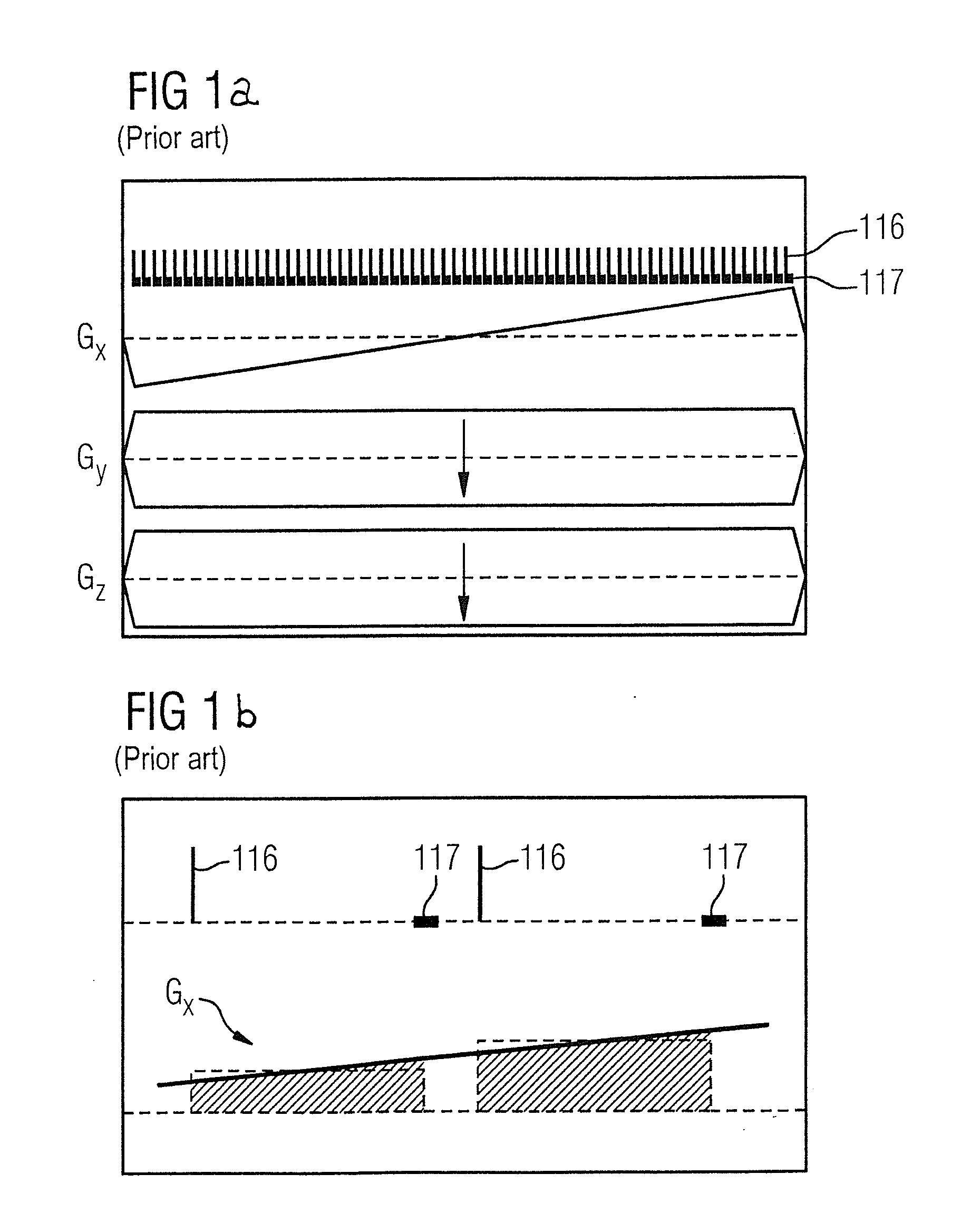
[0025]A sequence to acquire a line in k-space is shown in FIG. 1a, according to the know RASP method. It is apparent that the two phase coding gradients Gy and Gz are activated with a constant strength while the strength of the third phase coding gradient Gx increases continuously. For simplicity, no peripheral pulses 115 are drawn in this view.

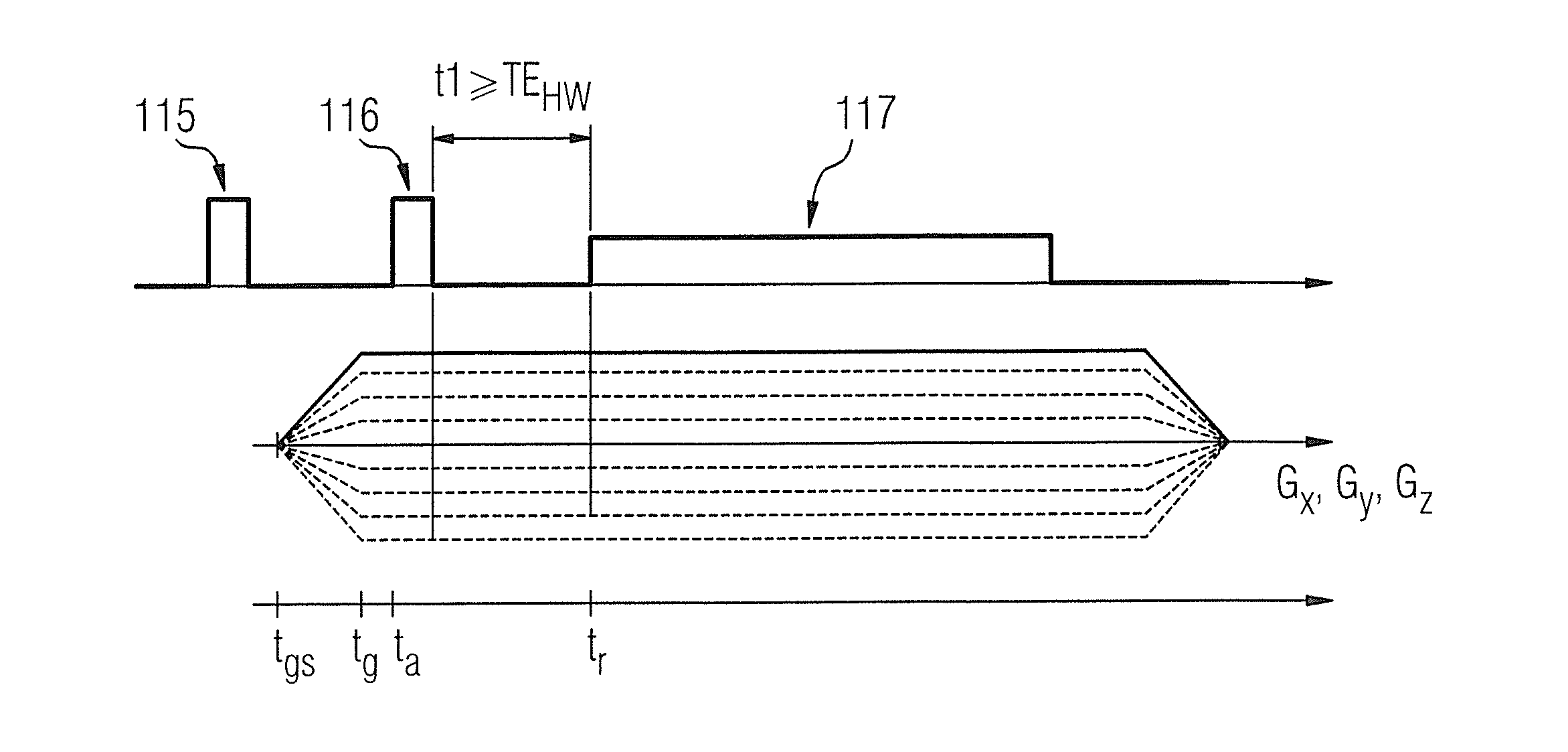
[0026]The acquisition of two raw data points in RASP is presented in detail in FIG. 1b. It is apparent that the echo time—i.e. the time interval from the RF excitation pulse 116 up to the beginning of the readout time period 117—is constant. Moreover, the phase coding gradient Gx runs in stages from the bottom upward. The phase coding gradient Gx to read out a raw data point is thereby kept constant, which means that the phase coding gradient Gx is kept constant for the time period TE (echo time). A preparation pulse 115 can be radiated every N RF excitation pulses 116, for example before the respective RF excitation pulse or also in combinat...


PUM


Abstract

In a method and magnetic resonance apparatus to generate magnetic resonance measurement data, k-space corresponding to the examination region is subdivided into a first region and a second region. The first region includes the k-space center, and a ratio of preparation pulses radiated by the radio-frequency antenna of the magnetic resonance apparatus to RF excitation pulses radiated by the radio-frequency antenna is greater in the first region than in a second region of k-space corresponding to the examination region that is not covered by the first region of k-space. Preparation pulses in the entirety of k-space corresponding to the examination region are therefore not radiated uniformly often, but instead a reduced number of preparation pulses is applied in the second region in comparison to the first region. The total measurement time to generate magnetic resonance data, as well as a SAR exposure, are reduced.

Description

BACKGROUND OF THE INVENTION[0001]1. Field of the Invention[0002]The invention concerns a method to generate, by means of a magnetic resonance system, magnetic resonance measurement data of an examination region to be examined that is located in a measurement volume of a magnetic resonance system by radiation of preparation pulses into the examination subject and readout of k-space corresponding to the examination region as well as a magnetic resonance system electronically readable data medium with programming instructions to implement such a method being stored therein.[0003]2. Description of the Prior Art[0004]Magnetic resonance (MR) is a known modality with which images of the inside of an examination subject can be generated. Expressed simply for this purpose, the examination subject is positioned within a strong, static, homogeneous basic magnetic field (also called a B0 field) with field strengths of 0.2 Tesla to 7 Tesla and more, such that the nuclear spins of the examination...

Claims


Application Information

Patent Timeline
IPC IPC(8): G01R33/44G01R33/341
CPCA61B5/055G01R33/288G01R33/4816G01R33/5615G01R33/4824G01R33/5602G01R33/5607G01R33/482
Inventor GRODZKI, DAVID
Owner SIEMENS HEALTHCARE GMBH
Why Eureka
Try Eureka