Amphibious platform vehicle-vessel

a technology of amphibious platforms and vehicles, which is applied in the direction of mechanical machines/dredgers, soil shifting machines/dredgers, transportation and packaging, etc., can solve the problems of cumbersome process of deployment and retracting of spuds, marsh buggies are limited in earth-moving operations, and vehicles aren't designed to operate while floating, so as to increase the stability of floating operations

Active Publication Date: 2022-06-07
WILSON SR JOHN M +3
View PDF35 Cites 4 Cited by
  • Summary
  • Abstract
  • Description
  • Claims
  • Application Information

AI Technical Summary

Problems solved by technology

Although marsh buggies are often capable of moving through any terrain, these vehicles aren't designed to operate while floating in water deeper than their pontoons.
Thus, marsh buggies are limited in performing earth-moving operations to dry land or relatively shallow water where their pontoons are resting on the ground.
Presently, deployment and retracting of the spuds can be a cumbersome process, especially under circumstances where spuds become stuck in muddy ground.
The use of spuds significantly slows down the ability to advance operations across a large area.
Spuds are effective for preventing movement across the water surface but are less effective in stabilizing against rocking motion caused either by swelling of the water surface or by operation of the excavation equipment.
Different moving-lifting equipment, while being similar in being hydraulically operated, requires different mounting hardware, making changing from one piece of equipment to another a complex endeavor that is difficult to accomplish at a remote worksite.
Such transport often involves some use of public roads and highways, which impose limitations of size and weight, which in turn might require partial disassembly of large heavy equipment and then reassembly at a remote and inconvenient worksite

Method used


Image

  • Amphibious platform vehicle-vessel
  • Amphibious platform vehicle-vessel
  • Amphibious platform vehicle-vessel

Examples


Embodiment Construction

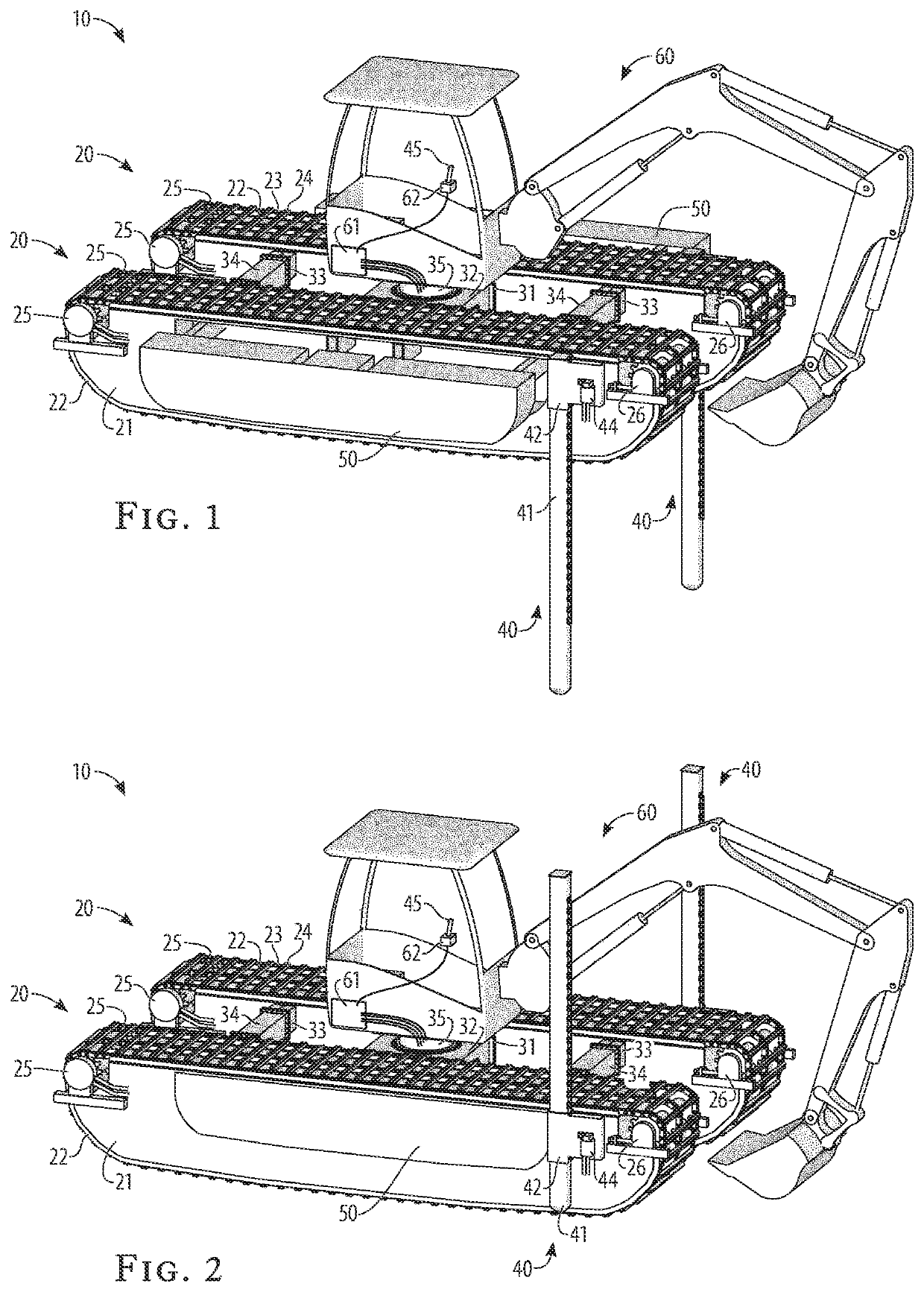
[0025]Referring to FIG. 1 and FIG. 2, the amphibious platform vehicle-vessel 10 provides for the use of moving-lifting equipment 60 on solid ground, semi-solid or marshy ground, shallow water, and deeper water. The moving-lifting equipment 60 can be of an excavator or backhoe type, as illustrated, or of a crane type. The different types and brands of moving-lifting equipment have different physical mounting configurations, and the amphibious platform vehicle-vessel 10 is adaptable to different equipment, as treated below. The amphibious platform vehicle-vessel 10 is modular and can be transported to or from a worksite as separate modules of size and weight appropriate to fit onto a truck trailer operating on existing roads and highways. The amphibious platform vehicle-vessel 10 provides for movement of mounted moving-lifting equipment 60 around a worksite, including movement between solid, marshy, and water surfaces.

[0026]The moving-lifting equipment 60 is hydraulically operated and...


PUM


Abstract

An amphibious platform vehicle-vessel to support and to move hydraulically operated and controlled earth-moving and lifting equipment, such as excavators and cranes, on solid ground, semi-solid or marshy ground, shallow water, and deeper water. The modular units can be transported to a worksite on separate trailers and assembled and reconfigured on site. Two compartmented pontoon units are mounted to an adaptive cross member that can accommodate different types of moving-lifting equipment through different mounting flanges, and to auxiliary cross members. Propulsion is provided through amphibious cleats on drive chains in chain tracks driven by dual-motor driving drums and over a tension-adjusting passive chain roller, surrounding a sealed pontoon shell internally reinforced with bulkhead partitions, beam shell-bottom stiffeners, and pressed-angle shell-bottom stiffeners. An extendable auxiliary float can be extended outward from each compartmented pontoon for increased stability in floating operations.

Description

BACKGROUND OF THE INVENTION[0001]This invention provides an amphibious platform vehicle-vessel to support and to move hydraulically operated and controlled earth-moving and lifting equipment, such as excavators and cranes, on solid ground, semi-solid or marshy ground, shallow water, and deeper water.[0002]Amphibious vehicles, known as marsh buggies, were first developed to support oil and gas exploration operations conducted in marshy or swampy terrain. Marsh buggies typically include a pair of pontoons connected to a center platform. The pontoons are usually surrounded by a cleated track system which is capable of engaging ground, water, or swamp land to propel the vehicle. The track system uses one or more endless chains surrounding the periphery of each pontoon. The endless chains, supporting the cleated tracks, are driven about the periphery of the pontoons, by a sprocket or other means, in order to provide propulsion to the vehicle. By varying the track speed around each pontoo...

Claims


Application Information

Patent Timeline
Patent Type & Authority Patents(United States)
IPC IPC(8): B60F3/00E02F9/06
CPCE02F9/062B60F3/0015B60F3/0038B62D55/00E02F3/32E02F9/2883E02F9/2275B62D63/025B62D57/02
Inventor WILSON, SR., JOHN M.WILSON, DEAN R.WILSON, JR., JOHN M.WILSON, ROBERT M.
Owner WILSON SR JOHN M
Why Eureka
Try Eureka