Bus bar module

a bus bar and module technology, applied in the field of bus bar modules, can solve the problems of unstable connection state of the bus bar to the electrodes by the nuts, and achieve the effect of not preventing elastic deformation, easy elastic deformation, and easy displacemen

Active Publication Date: 2022-06-21
YAZAKI CORP
View PDF9 Cites 2 Cited by
  • Summary
  • Abstract
  • Description
  • Claims
  • Application Information

AI Technical Summary

Benefits of technology

[0013]According to the bus bar module having the configuration (1), when the electrode is fixed to the electrical connection portion of the bus bar to electrically connect the bus bar to the electrode, the projection of the bus bar supported on the support portion is easily elastically deformed. Therefore, even if displacement in an assembling direction of the bus bar occurs between the electrodes of the adjacent single cells, it is possible to easily absorb the displacement by the elastic deformation of the projection. In this case, the support portion has the width smaller than the interval between the inner side surfaces of the side plate portions of the projection, so that side surfaces of the support portion do not abut against the inner surfaces of the side plate portion of the projection, and thus do not prevent the elastic deformation. Accordingly, when the bus bar is electrically connected to the electrode, it is possible to constantly and stably fix the electrical connection portion to the electrode with a predetermined fixing force and to attain good connection reliability.
[0014]According to the bus bar module having the configuration (2), the support portion is in line contact with the back surface of the projection in the direction orthogonal to the arrangement direction of the electrical connection portions. Accordingly, when the bus bar is electrically connected to the electrode in a state in which the displacement in the assembling direction of the bus bar has occurred between the electrodes of the adjacent single cells, it is possible to easily incline the bus bar using a part thereof in contact with the support portion as a fulcrum. Accordingly, it is possible to more easily absorb the displacement between the electrodes of the single cells.
[0015]According to the bus bar module having the configuration (3), when the bus bar is fixed to the electrodes of the single cells with three or more electrical connection portions, the displacement in the assembling direction of the bus bar is likely to occur among the electrodes of three or more adjacent single cells. However, the projection of the bus bar formed between the electrical connection portions is supported on the support portion. Accordingly, even if the displacement occurs among the electrodes fastened in the electrical connection portions, it is possible to elastically deform the projection supported by the support portion between the electrical connection portions to easily absorb the displacement.
[0016]According to the present invention, it is possible to provide a bus bar module in which a bus bar can be smoothly and stably fixed and electrically connected to an electrode of a single cell of a battery assembly.

Problems solved by technology

Then, when the electrodes of the adjacent single cells are connected to one another by the bus bar, a fastening position may be shifted in a height direction, and a fastening state of the bus bar to the electrodes by the nuts may become unstable.

Method used


Image

  • Bus bar module
  • Bus bar module
  • Bus bar module

Examples


Embodiment Construction

[0025]Hereinafter, an embodiment of the present invention will be described with reference to the drawings.

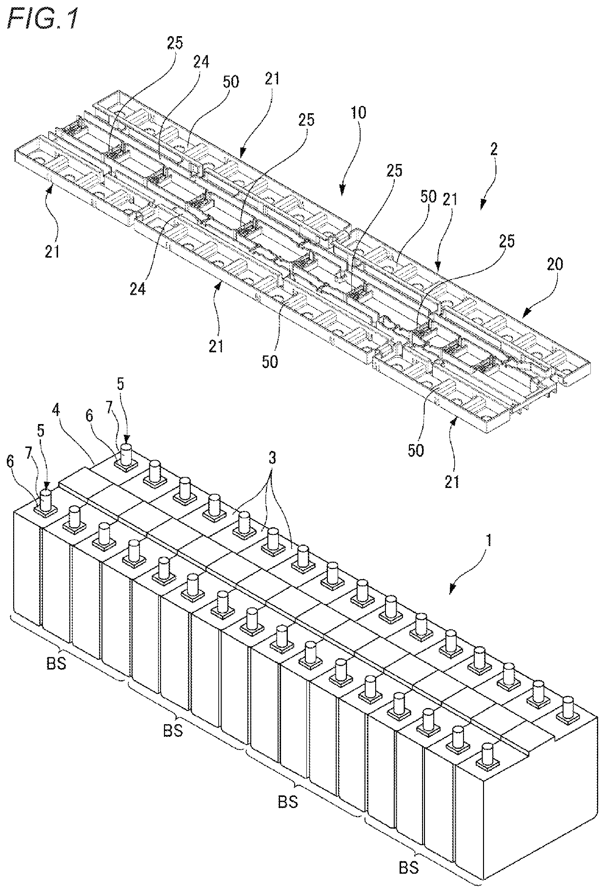
[0026]FIG. 1 is a perspective view of a bus bar module and a battery assembly according to the present embodiment.

[0027]As illustrated in FIG. 1, the bus bar module 10 according to the present embodiment is assembled to an upper part of a battery assembly 1 to form a power supply device 2. The power supply device 2 is mounted and used on various vehicles which are an electric automobile that travels using an electric motor, a hybrid automobile that travels using an engine and an electric motor in combination, and the like, and is configured to supply power to the electric motor.

[0028]The battery assembly 1 includes a plurality of single cells 3 that are arranged in a row along one direction and are fixed to one another. Each single cell 3 includes a rectangular parallelepiped battery body 4, and a pair of electrodes 5 protruding from near one end of an upper surface of the batt...


PUM

PropertyMeasurementUnit
conductiveaaaaaaaaaa
widthaaaaaaaaaa
heightaaaaaaaaaa

Abstract

A bus bar includes a plurality of fastening holes in which a plurality of electrodes of a single cell is fastened with a nut, and a plurality of projections formed between the fastening holes and projecting in a direction away from the single cell. A case includes a bus bar hosing portion in which the bus bar is housed, and a support portion disposed in the projection of the bus bar housed in the bus bar housing portion and abutting against a back surface of the projection to support the bus bar. The support portion has a width smaller than an interval between inner side surfaces of side plate portions of the projection.

Description

CROSS-REFERENCE TO RELATED APPLICATIONS[0001]This application is based on and claims priority under 35 USC 119 from Japanese Patent Application No. 2019-112848 filed on Jun. 18, 2019, the contents of which are incorporated herein by reference.TECHNICAL FIELD[0002]The present invention relates to a bus bar module.BACKGROUND ART[0003]For example, a power supply device mounted on various vehicles which are an electric automobile that travels using an electric motor, a hybrid automobile that travels using an engine and an electric motor in combination, and the like includes a bus bar module including a bus bar connected to electrodes of a plurality of single cells of a battery assembly and a case that houses the bus bar and guides a routing path of an electric wire extending from the bus bar or the like (for example, see Patent Literature 1). The bus bar of the bus bar module is supported from below by a plate-shaped support portion provided in the case, and is fastened to the electrode...

Claims


Application Information

Patent Timeline
Patent Type & Authority Patents(United States)
IPC IPC(8): H01M10/48H01M10/42H01M50/502H01M50/531H01M50/20H01M50/209H01M50/507H01M50/517H01M50/522H01M50/524
CPCH01M50/502H01M10/425H01M10/482H01M50/20H01M50/531H01M2220/20H01M10/63H01M50/507H01M50/522H01M50/517H01M50/209H01M50/524Y02E60/10
Inventor OKAZAKI, YUTAROYANAGIHARA, SHINICHI
Owner YAZAKI CORP
Why Eureka
Try Eureka