Tire noise reduction device and pneumatic tire provided with same

a technology of noise reduction device and pneumatic tire, which is applied in the direction of instruments, transportation and packaging, synthetic resin layered products, etc., can solve the problems of noise generation, sound absorbing member warpage, and breakage so as to reduce noise generation, reduce noise generation, and improve the durability of sound absorbing member with respect to the friction of the band member

Active Publication Date: 2022-06-28
THE YOKOHAMA RUBBER CO LTD
View PDF25 Cites 0 Cited by
  • Summary
  • Abstract
  • Description
  • Claims
  • Application Information

AI Technical Summary

Benefits of technology

[0005]The present technology provides a tire noise reduction device that can improve high-speed durability performance by inhibiting breakage of a sound absorbing member and damage to a tire inner surface that are caused by friction between a band member and the sound absorbing member and between the band member and the tire inner surface, and a pneumatic tire provided with the tire noise reduction device.
[0009]In the present technology, it is preferable that each of the chamfered portions in the band member be formed as a flat surface, and that an angle θ1, with respect to the width direction of the band member, of a chamfered portion C1 positioned on an inner circumferential surface side of the band member, and an angle θ2, with respect to the width direction of the band member, of a chamfered portion C2 positioned on an outer circumferential surface side of the band member be respectively set to be in a range of 110°≤θ1≤160° and 110°≤θ2≤160°. By forming the chamfered portions C1 and C2 in this way, the breakage of the sound absorbing member and the damage to the tire inner surface that are caused by the friction between the band member and the sound absorbing member and between the band member and the tire inner surface can be more effectively inhibited. Both the angles θ1 and θ2 of the chamfered portions C1 and C2 are more preferably set to be in a range from 135° to 160°.
[0010]In the present technology, the angle θ1 is preferably larger than the angle θ2. Since durability of the sound absorbing member is lower than that of the tire inner surface with respect to the friction with the band member, by making the angle θ1 of the chamfered portion C1 on the sound absorbing member side relatively larger, the durability of the sound absorbing member with respect to the friction with the band member is improved. On the other hand, by making the angle θ2 of the chamfered portion C2 on the tire inner surface side relatively smaller, a cross-sectional area of the band member is made as large as possible, and thus, weakening of strength of the band member can be minimized.
[0011]In the present technology, it is preferable that each of the chamfered portions in the band member be formed as a curved surface, and that a radius of curvature r1 of a chamfered portion R1 positioned on the inner circumferential surface side of the band member, and a radius of curvature r2 of a chamfered portion R2 positioned on an outer circumferential surface side of the band member be respectively set to be in a range of 0.1 TB≤r1≤0.5 TB and 0.1 TB≤r2≤0.5 TB with respect to a thickness TB of the band member. By forming the chamfered portions R1 and R2 in this way, the breakage of the sound absorbing member and the damage to the tire inner surface that are caused by the friction between the band member and the sound absorbing member and between the band member and the tire inner surface can be more effectively inhibited. The radii of curvature r1 and r2 are more preferably set to be in a range of 0.3 TB≤r1≤0.5 TB and 0.3 TB≤r2≤0.5 TB, respectively.
[0012]In the present technology, the radius of curvature r1 is preferably larger than the radius of curvature r2. Since the durability of the sound absorbing member is lower than that of the tire inner surface with respect to the friction with the band member, by making the radius of curvature r1 of the chamfered portion R1 on the sound absorbing member side relatively larger, the durability of the sound absorbing member with respect to the friction with the band member is improved. On the other hand, by making the radius of curvature r2 of the chamfered portion R2 on the tire inner surface side relatively smaller, the cross-sectional area of the band member is made as large as possible, and thus, the weakening of the strength of the band member can be minimized.

Problems solved by technology

Cavernous resonance, which is caused by vibration of air inflating a tire cavity portion, is one cause of tire noise.
However, when the elastic fixing band has a rectangular cross-section, the sound absorbing member is caused to warp due to the centrifugal force when the vehicle is driven for a long time in a high-speed region.
As a result, friction occurs between edge portions of the elastic fixing band and the sound absorbing member and between edge portions of the sound absorbing member and the tire inner surface, and breakage of the sound absorbing member and damage to the tire inner surface may occur.

Method used


Image

  • Tire noise reduction device and pneumatic tire provided with same
  • Tire noise reduction device and pneumatic tire provided with same
  • Tire noise reduction device and pneumatic tire provided with same

Examples


examples

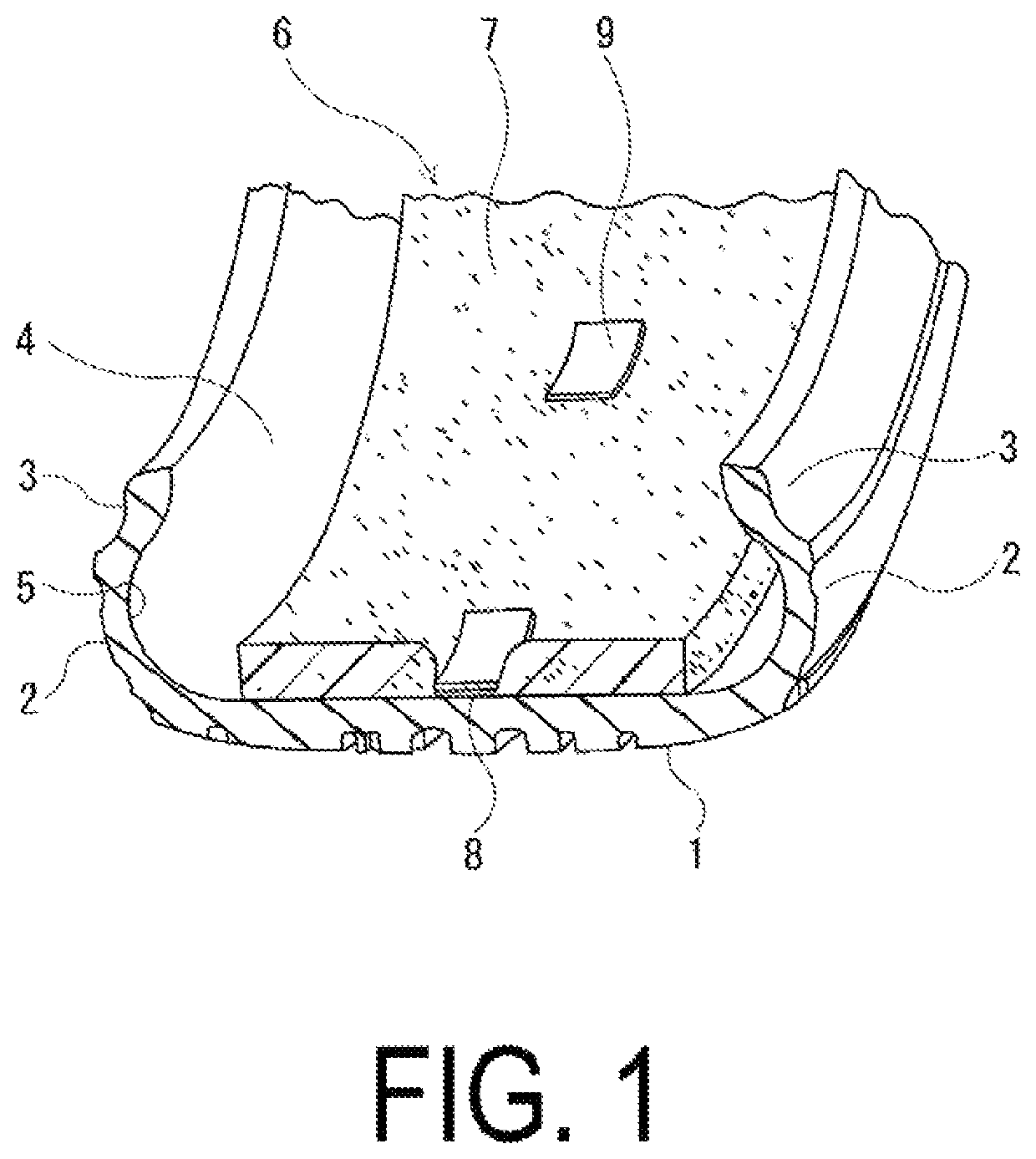
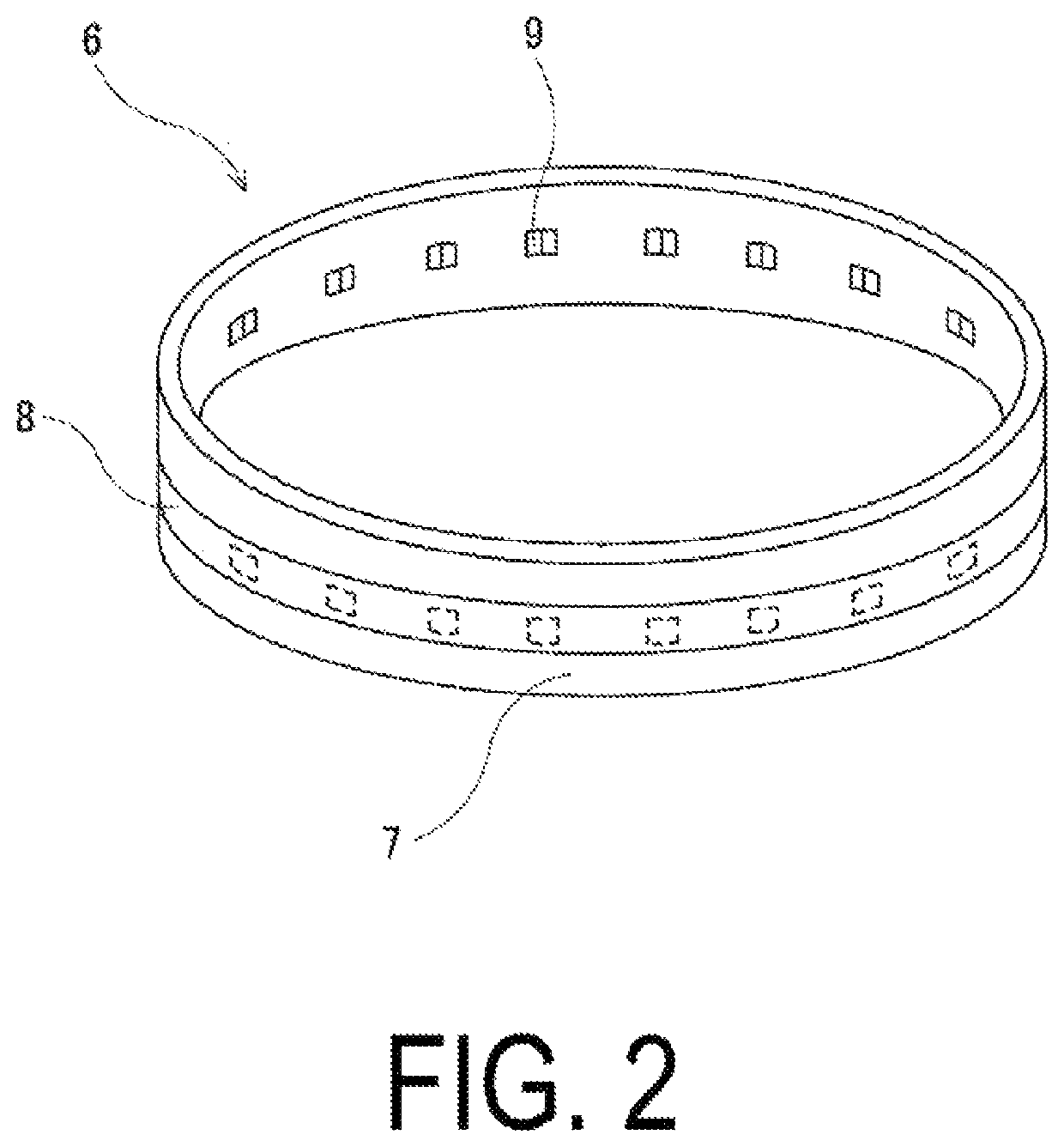
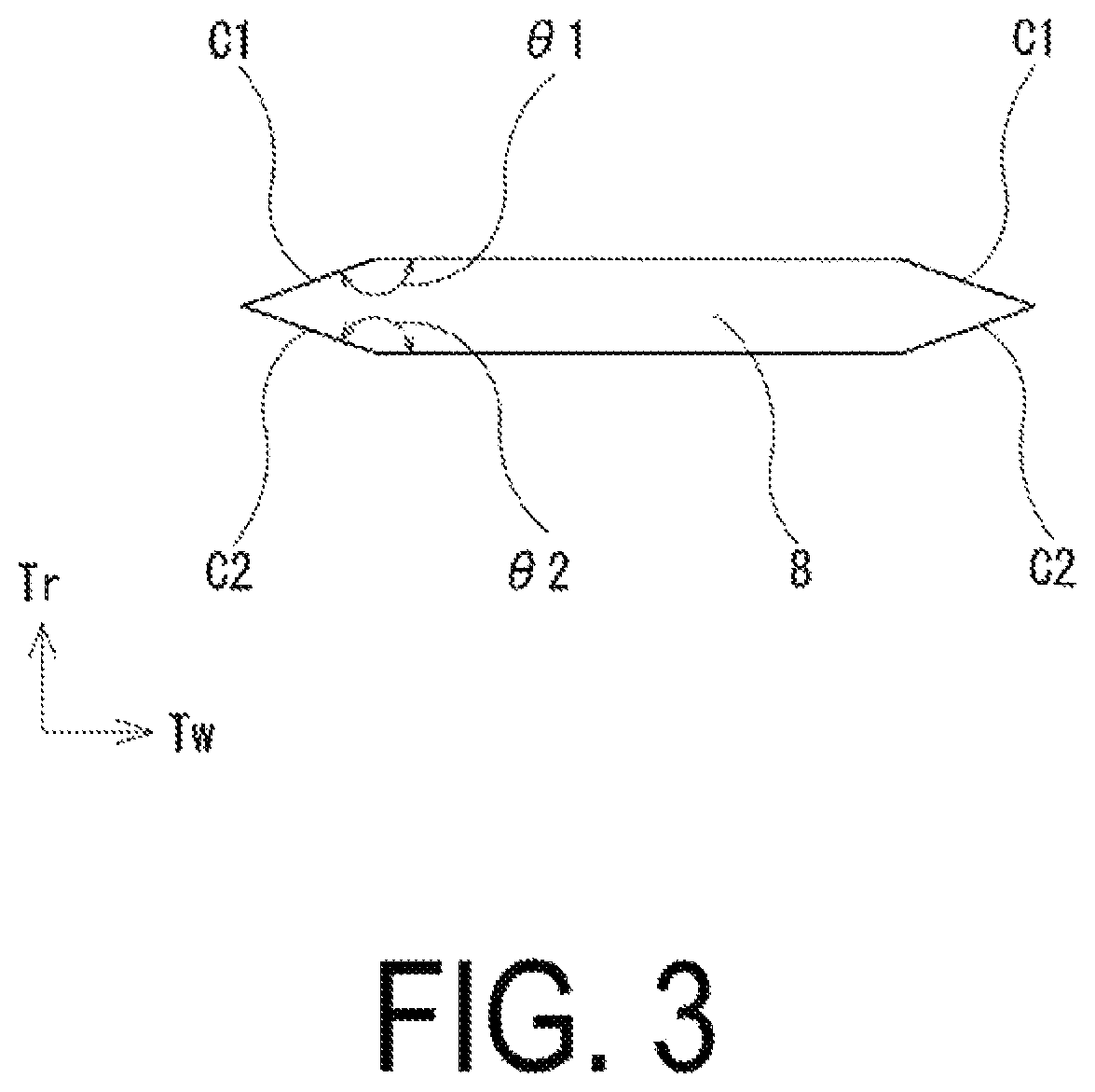
[0034]In a tire noise reduction device provided with a sound absorbing member made of a porous material and a band member provided for attaching the sound absorbing member to a tire inner surface and disposed between the sound absorbing member and the tire inner surface, Comparative Examples 1 to 4 and Examples 1 to 5 of noise reduction devices, in which chamfered portions formed as flat surfaces were formed in the band member, were manufactured, the chamfered portions of the band member having various different configurations. Further, Conventional Example 1 was prepared as a known noise reduction device in which the chamfered portions were not provided in the band member. These noise reduction devices are suitable for a pneumatic tire of a tire size of 245 / 50R18.

[0035]In Comparative Examples 1 to 4 and Examples 1 to 5, the presence of the chamfered portions, positions of the chamfered portions (in the width direction of the band member), positions of the chamfered portions (in the...


PUM

PropertyMeasurementUnit
angles θ1aaaaaaaaaa
angleaaaaaaaaaa
angles θ1aaaaaaaaaa

Abstract

A tire noise reduction device includes a sound absorbing member made of a porous material; and a band member disposed between the sound absorbing member and the tire inner surface and provided for attaching the sound absorbing member to a tire inner surface, the band member including chamfered portions on both surface sides at both ends in a width direction of the band member.

Description

TECHNICAL FIELD[0001]The present technology relates to a device for reducing cavernous resonance generated in a pneumatic tire, and more specifically relates to a tire noise reduction device that can improve high-speed durability performance by inhibiting breakage of a sound absorbing member and damage to a tire inner surface that are caused by friction between a band member and the sound absorbing member and between the band member and the tire inner surface, and a pneumatic tire provided with the tire noise reduction device.BACKGROUND ART[0002]Cavernous resonance, which is caused by vibration of air inflating a tire cavity portion, is one cause of tire noise. The cavernous resonance occurs as a result of a tread portion of a tire, which is in contact with a road surface when a vehicle is driven, vibrating due to unevenness of the road surface, and the vibration causing the air inside the tire cavity portion to vibrate. Of the cavernous resonance, there is a frequency band that is ...

Claims


Application Information

Patent Timeline
Patent Type & Authority Patents(United States)
IPC IPC(8): B60C19/00B60C5/00G10K11/168B32B5/00G10K11/16F16F15/10B32B5/18B32B27/06
CPCB60C19/002B32B5/00B32B5/18B32B27/06B32B27/065B60C5/00F16F15/10G10K11/16G10K11/168Y10T428/249953
Inventor NARUSE, MASAHIRO
Owner THE YOKOHAMA RUBBER CO LTD
Why Eureka
Try Eureka