Simple sound control of underwater lights

Active Publication Date: 2022-06-28
KELDAN GMBH
View PDF8 Cites 0 Cited by
  • Summary
  • Abstract
  • Description
  • Claims
  • Application Information

AI Technical Summary

Benefits of technology

The patent describes an invention that allows sound to easily travel through water. The invention includes a microphone placed in an air space inside a light housing. When sound waves hit the outside of the light, they can be transmitted to the microphone. The invention also allows for adjustable settings for different frequencies, as well as a reset function in case of out-of-sync balancing between the lights. This invention can help to isolate lights and respond to only specific commands.

Problems solved by technology

With only two hands it is awkward to reach to each light and adjust the settings.
These controls are limited by the limited ability of RF frequencies to travel any distance underwater.
They also require more expensive electronics.
Cabled systems are inexpensive but subject to the challenges of working with cables and connectors that can be dislodged and otherwise impaired to thereby disrupt the signals.

Method used


Image

  • Simple sound control of underwater lights
  • Simple sound control of underwater lights
  • Simple sound control of underwater lights

Examples


Embodiment Construction

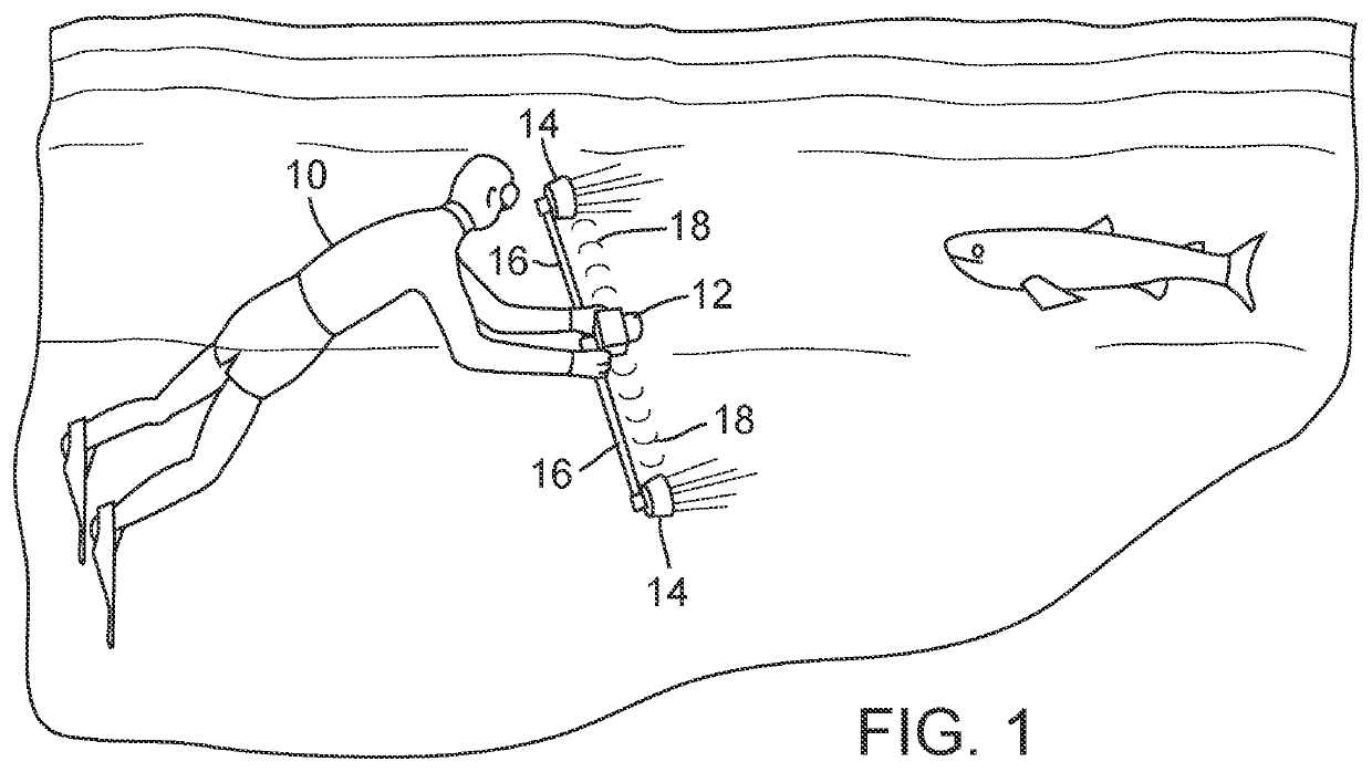
[0016]In the drawings FIG. 1 shows a diver 10 engaged in underwater photography or videography using a camera 12. The camera is accompanied by lights 14 attached via outriggers 16, so as to be spaced some distance left and right of the camera. At 18 are indicated sound waves traveling through the water for control of the lights via inputs on a control module on or at the camera.

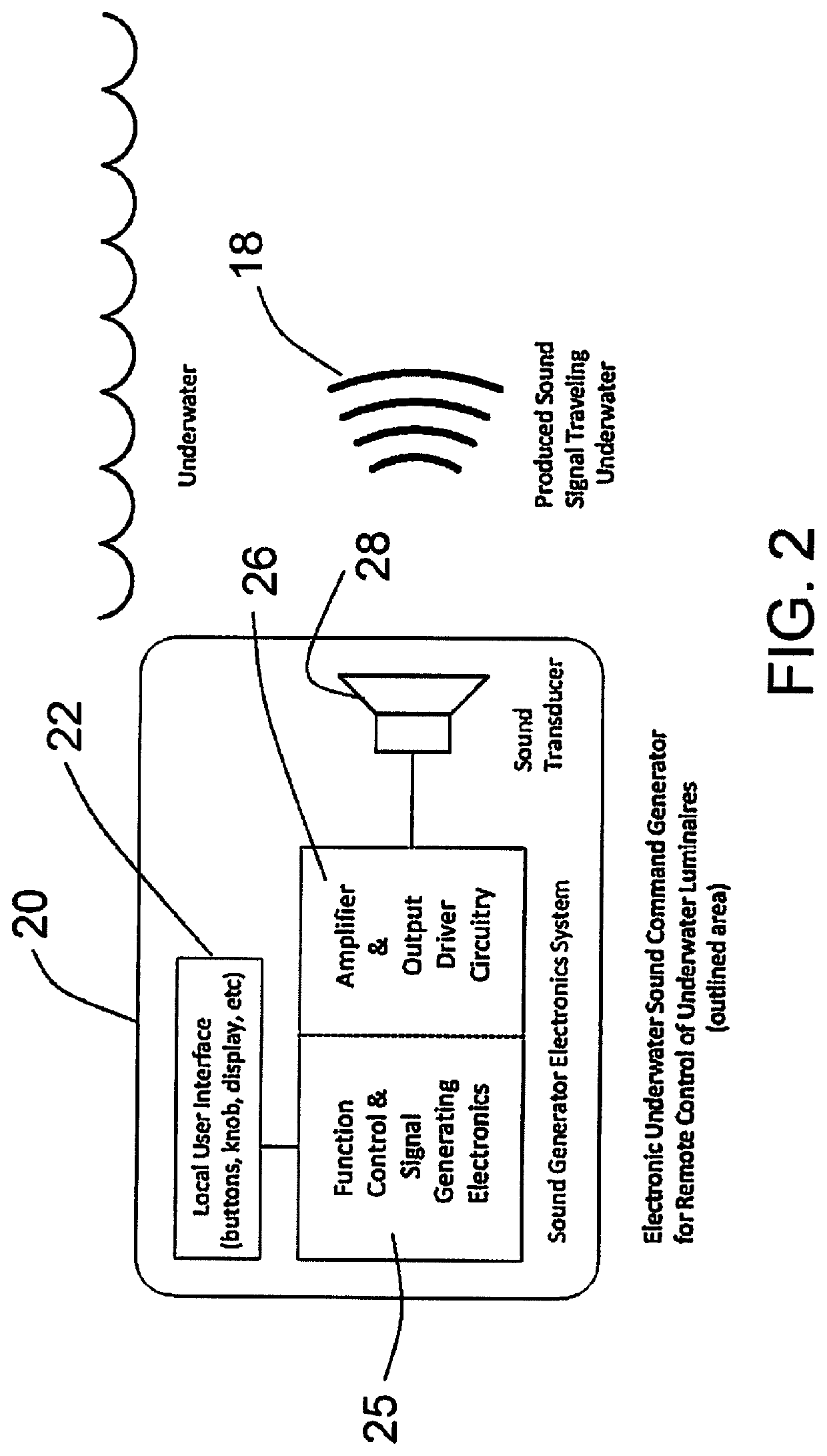
[0017]FIG. 2 indicates the user's control module 20, which is on the camera or comprises a waterproof case attached to the camera. User input user interface control buttons or knobs, and preferably a display, are indicated at 22. These can be for turning the lights on and off, and / or for controlling light intensity or mode, such as steady or pulsing and potentially light color. The display can indicate selections to be made or status of the lights. In one embodiment the user input could be a single button, wherein successive depressions of the button will sequence through a series of light settings (which can...


PUM


Abstract

A control system for underwater diving lights utilizes sounds of specific frequency emitted by action of a diver to control one or more remotely positioned diving lights.

Description

[0001]This application claims benefit of provisional application Ser. No. 63 / 035,608, filed Jun. 5, 2020.BACKGROUND OF THE INVENTION[0002]This invention describes a method to control the output of lights used for imaging such as photography lights or video lights and other applications underwater.[0003]When shooting video or photos underwater a diver typically carries a camera housing with two or more lights attached to the housing on arms that can be up to 3 to 4 feet in length, extending out from either side of the camera housing. In other cases lights may be set at a point some distance from the camera such as for lighting a wreck where lights are placed inside the wreck and the images are taken from a distance to capture the complete scene.[0004]The lights need to be turned on / off as well as adjusted when on to achieve the ideal exposure. With only two hands it is awkward to reach to each light and adjust the settings. Remote control would be useful. In the case of lights placed...

Claims


Application Information

Patent Timeline
IPC IPC(8): H05B47/12G03B15/03F21V31/00
CPCH05B47/12G03B15/03F21V31/005F21L4/00F21V23/045G03B17/08G03B31/00
Inventor TOLAN, DAVID W.LAME, BROOKS P.GOLDMAN, JOSEPH G.MCKEE, DEVIN P.EMERSON, DANIEL T.
Owner KELDAN GMBH
Why Eureka
Try Eureka