
Method and device for non-reciprocal transmission of electromagnetic radiation beam

Active Publication Date: 2020-01-09
UAB ATZALAS
View PDF0 Cites 0 Cited by
  • Summary
  • Abstract
  • Description
  • Claims
  • Application Information

AI Technical Summary

Benefits of technology

The proposed invention is a device that uses a rotating ring interferometer, which is different from other types of interferometers because it is not sensitive to changes in the reflectors or other elements of the device. This makes it easier to ensure the required phase difference between the beams. The device also is not sensitive to environmental disturbances, vibration, or temperature fluctuations. Additionally, the device contains no magnets, which means there are no special safety measures needed when working with it.

Problems solved by technology

The disadvantage of this known method and device is that the isolator remains functional only within a certain range limited by the wavelength, because the magneto-optical crystal remains transparent only to certain wavelengths.
Moreover, the Verdet constant that defines the polarization rotation angle depending on the magnetic field is not big enough for just any wavelength to enable its use in practical applications.
Moreover, the price of the magneto-optical crystal is relatively high.
Clearly this is almost impossible to embody.
The disadvantage of this known method and device is that it is practically impossible to produce a device with mechanically controlled half-wave plates while an electrically controlled device with electro-optical crystals is a very complex and impractical solution.
Moreover, despite the fact that electro-optical crystals can have fast controls they are not suitable for high-frequency switching, because they easily get overheated.
In addition, the electro-optical crystals used to produce the device are expensive.
As a result, there is a constructive interference of the light beams propagating in forward direction and a destructive interference of the light beams propagating in backward direction in the two branches of the interferometer.
The disadvantage of this known method and device is that it is suitable only for use in integrated schemes and only under low average radiation power.
It is rather complicated to produce the isolator of the kind suitable for use under high average radiation power.
Another disadvantage of this known method and device is that it is based on the Mach-Zehnder interferometer which makes it necessary to ensure that the optical path length be equal along both branches of the interferometer and do it at a much greater accuracy than when determining the length of the radiation wave and make sure that it does not change with time.
The disadvantage of this known method and device is that the magneto-optical material used for the purpose of the device remains transparent only within a limited wavelength range.
Moreover, in case of some wavelengths the Verdet constant, which defines the rotation angle of polarization depending on the magnetic field, is simply not big enough.
Moreover, the price of the magneto-optical material is relatively high.
Another disadvantage of this known method and device is that it is based on the Mach-Zehnder interferometer which makes it necessary to ensure that the optical path length be equal along both branches of the interferometer and do it at a much greater accuracy than when determining the length of the radiation wave and make sure that it does not change with time.
This is rather complicated to ensure in case of non-integrated Mach-Zehnder interferometers, therefore, it is complicated to create a powerful non-reciprocal transmission device by using this method.
Moreover, the cost price of the device is lower compared to other analogous devices with the same parameters, because no magneto-optical crystals are used to produce it.

Method used


Image

  • Method and device for non-reciprocal transmission of electromagnetic radiation beam
  • Method and device for non-reciprocal transmission of electromagnetic radiation beam
  • Method and device for non-reciprocal transmission of electromagnetic radiation beam

Examples


Embodiment Construction

OF EMBODIMENT OF THE INVENTION

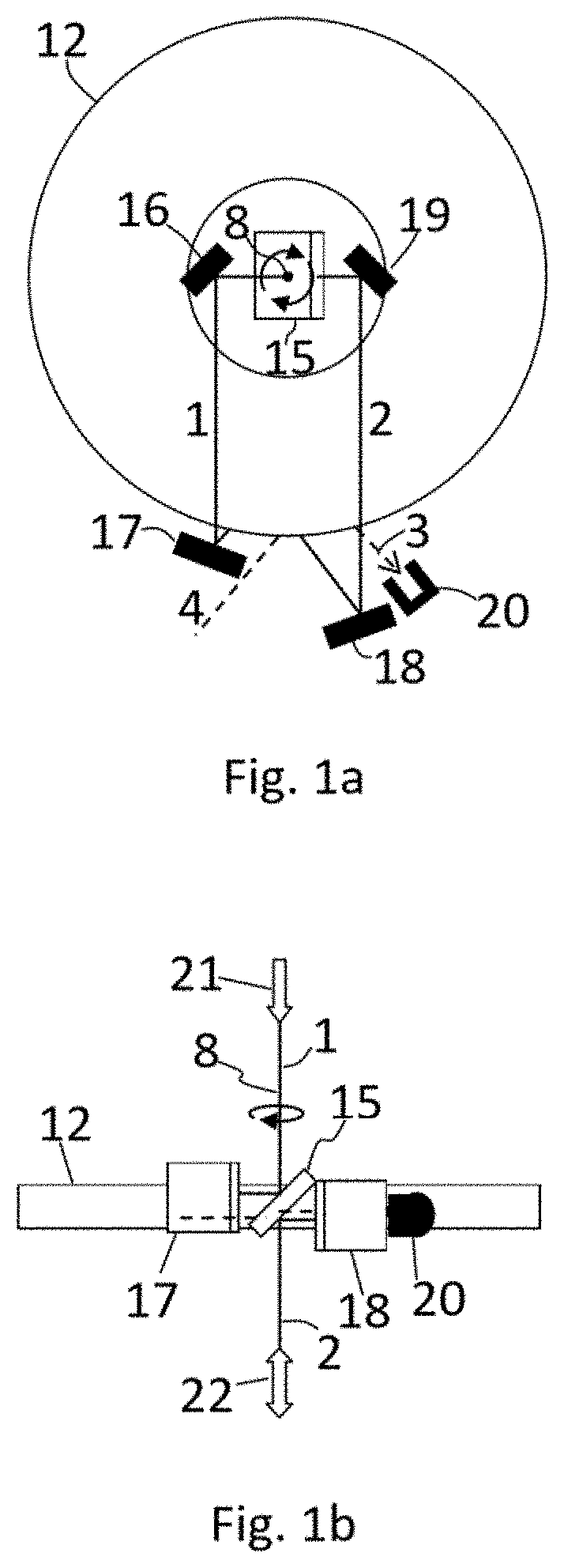
[0101]The propagation / transmission / input / output path of EMR beam defines the direction in which the EMR beam propagates, its position in space and state of polarization. Even though geometrically EMR beams can overlap, orthogonally polarized EMR beams have different propagation / transmission / input / output paths, because orthogonally polarized beams can have different refraction indexes due to anisotropy of materials. Moreover, orthogonally polarized beams can be separated with the help of wave plates and a polarizing beam splitter and directed along different geometrical paths.

[0102]The proposed method for non-reciprocal transmission of EMR beam comprises the following steps: EMR beam by any preselected path of input / output paths (1, 2, 3, 4) is directed to a rotating ring interferometer 12, which rotates at the angular velocity Ω, where with the help of a beam splitter 5 it is split into two equally or nearly equally intensive counter-propagating EMR bea...


PUM


Abstract

An electromagnetic radiation beam is inputted into a ring interferometer rotating at the angular velocity Ω where the beam is split into two equally intensive counter—propagating electromagnetic beams. The Sagnac Effect results in the phase shift of ±Pi / 2 radians, which may be either positive or negative depending on the direction in which the counter-propagating electromagnetic radiation beams propagate with regard to the rotation direction of the ring interferometer. An additionally phase shift of Pi / 2 radians is induced between the counter-propagating electromagnetic radiation beams inside the ring interferometer results in a total phase shift of either Pi radians or 0. The counter-propagating electromagnetic radiation beams inside the ring interferometer are then combined into one single electromagnetic radiation (EMR) beam which outputted from the rotating ring interferometer by using a different path than the one through which the EMR beam is inputted into it.

Description

TECHNICAL FIELD TO WHICH INVENTION RELATES[0001]The invention relates to the field of optical technology encompassing areas of terahertz, infrared, ultraviolet and extreme ultraviolet radiation technologies and is designed for the purpose of non-reciprocal transmission of electromagnetic radiation (EMR) beam method and device. It can be used where it is necessary to transmit the EMR beam forward by preventing reverse transmission. For example, non-reciprocal transmission devices are used as isolators or valves permitting an EMR beam to propagate in one direction only and the EMR beam propagating in the reverse direction is either blocked or diverted to a beam trap and never reaches the isolator entrance. Three- or four-port devices are used as circulators. For example, a three-port circulator directs an EMR beam from the first port to the second port and from the second port to the third port. Circulators are used in various laser amplification schemes, pulse stretching and compress...

Claims


Application Information

Patent Timeline
IPC IPC(8): G02B6/27G02B6/293
CPCG02B6/2746G02B6/29347
Inventor REGELSKIS, KESTUTIS
Owner UAB ATZALAS
Learn More