Impedance matching means between antenna and transmission line

Inactive Publication Date: 2006-05-18
HON HAI PRECISION IND CO LTD
View PDF3 Cites 7 Cited by
  • Summary
  • Abstract
  • Description
  • Claims
  • Application Information

AI Technical Summary

Benefits of technology

[0007] An impedance matching means according to the present invention is used with an antenna and is realized by a parasitic element for tuning an impedance of the antenna. The antenna comprises a grounding plate, a radiating body arranged on the grounding plate and a transmission line coupled to said radiating body and grounding plate. The parasitic element fo

Problems solved by technology

This can set up standing waves in the line and can also cause overheating in the transmitter o

Method used


Image

  • Impedance matching means between antenna and transmission line
  • Impedance matching means between antenna and transmission line
  • Impedance matching means between antenna and transmission line

Examples


Example

[0014] Reference will now be made in detail to a preferred embodiment of the present invention.

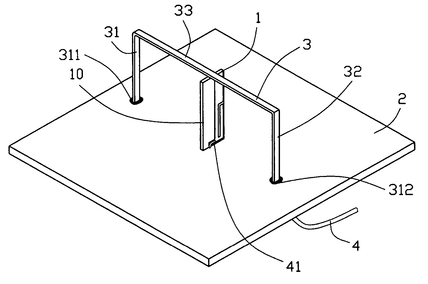
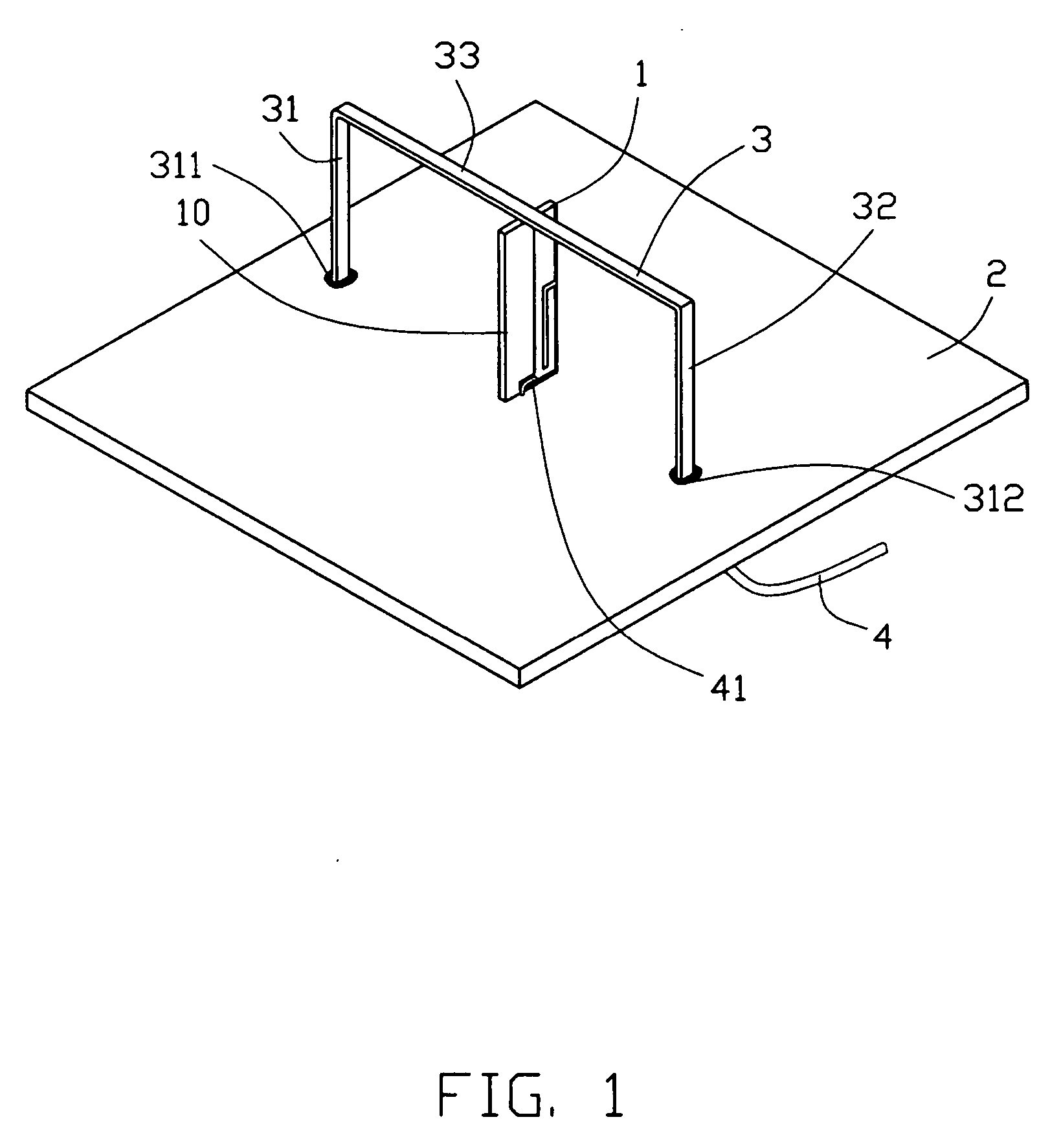
[0015] Referring to FIG. 1, an antenna comprises a radiating body 1, a grounding plate 2 and a coaxial cable 4. The radiating body 1 is arranged on the grounding plate 2 and power energy is supplied thereto by the coaxial cable 4. An impedance matching means is realized by a parasitic element 3, which is arranged on the grounding plate 2 as well.

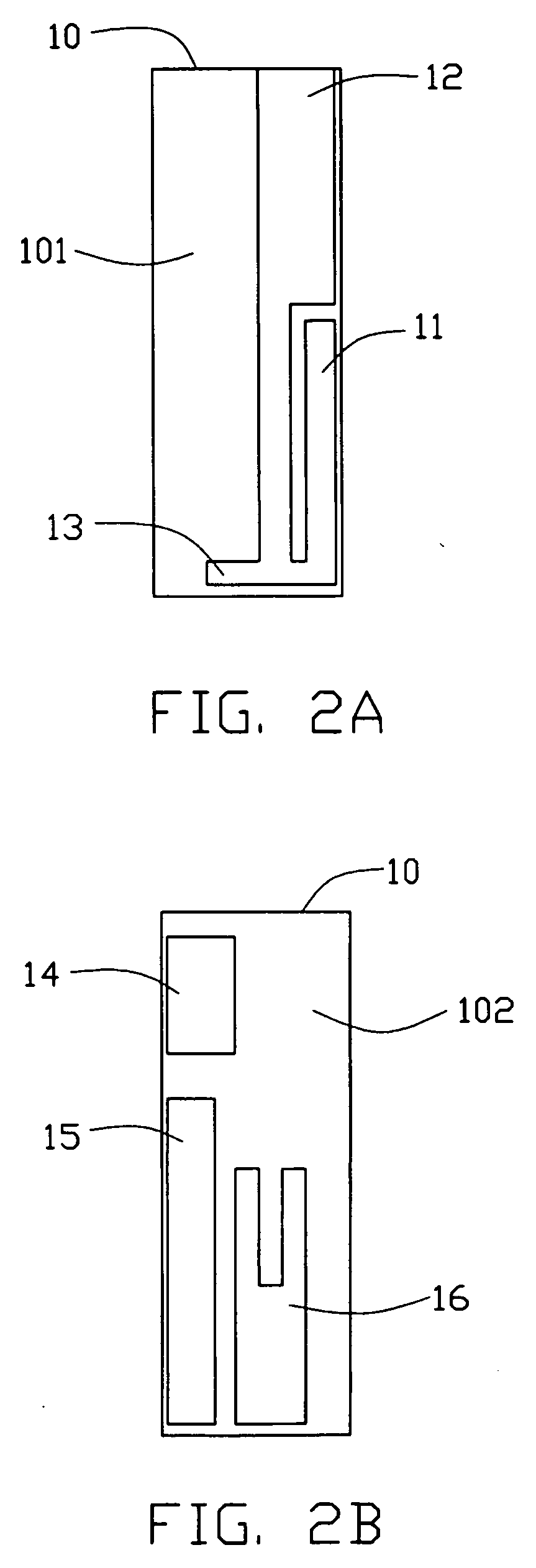
[0016] The radiating body 1 is formed of a metal foil fabricated on a dielectric substrate 10 thereof. The dielectric substrate 10 is disposed perpendicularly on the grounding plate 2. The area of the grounding plate 2 is much greater than that of the dielectric substrate 10. In this way, the grounding plate 2 provides a mirror image for the radiating body 1 above it so that it is as if another radiating body 1 is located below the grounding plate 2. The parasitic element 3 positioned on the grounding plate 2 crosses the radiating body 1 and is u...


PUM


Abstract

An impedance matching means according to the present invention is used with an antenna and is realized by a parasitic element (3) for tuning an impedance of the antenna. The antenna comprises a grounding plate (2), an radiating body (1) arranged on the grounding plate (2) and a transmission line (4) coupled to said radiating body (1) and grounding plate (2). The parasitic element (3) formed of a narrow metal sheet and configured as a bridge shape is arranged on the grounding plate (2). The parasitic element (3) has a first and a second ends (311, 321), both of which are electrically connected to the grounding plate (2). The arrangement of the parasitic element (3) results in a change of the impedance of the antenna, so the impedance matching between the antenna and the transmission line (4) can be achieved.

Description

BACKGROUND OF THE INVENTION [0001] 1. Field of the Invention [0002] The present invention relates generally to an impedance matching means, and more particularly to an impedance matching means between an antenna and a transmission line. [0003] 2. Description of the Prior Art [0004] In many RF situations, there is a relatively fixed load impedance—say a resonant antenna with a fixed impedance. A transmission line, such as a coaxial cable providing power energy to the antenna has its own characteristic impedance. In most cases when the energy reaches the end of the cable, we want as much as possible to transfer into our load—the antenna, in the case of a transmitter, or the input RF stage in the case of a receiver. For a transmitter this gives the highest power efficiency, while for a receiver this gives the best noise performance. To ensure this optimum energy transfer, we need to match the characteristic impedance of the cable to the impedance of the load. So for a 75 Ω antenna, we ...

Claims


Application Information

Patent Timeline
IPC IPC(8): H01Q1/50H01Q5/10
CPCH01Q9/36H01Q19/26
Inventor SU, WEN FONGKE, YUN-LONGHUANG, YAO-SHIEN
Owner HON HAI PRECISION IND CO LTD
Why Eureka
Try Eureka