
Portable pneumatic loading system for simulating operation of subway train

a technology of pneumatic loading system and subway train, which is applied in the direction of transportation and packaging, instruments, and ways, can solve the problems of affecting the normal operation of precise instruments and devices, affecting the normal use of special functional buildings such as hospitals, opera houses and laboratories, and structural damage or construction damage to buildings

Active Publication Date: 2022-07-19
ZHEJIANG UNIV CITY COLLEGE
View PDF3 Cites 2 Cited by
  • Summary
  • Abstract
  • Description
  • Claims
  • Application Information

AI Technical Summary

Benefits of technology

[0007]An object of the present invention is to provide a portable pneumatic loading system for simulating the operation of a subway train, which simulates real vibration characteristics of subways and can output the magnitude and frequency of the impact force.
[0017]Compared with the prior art, the present invention has the following advantages.
[0018]In the portable pneumatic loading system for simulating the operation of a subway train provided by the present invention, the device is light, flexible and portable, and can enter subway tunnels under various working conditions; the design is novel and reasonable, the operation is simple, and the actual engineering operation is highly feasible; the impact force and impact speed that are adjustable in magnitude and frequency can be output, the actual operation process is more rigorous, and the on-site adjustment process is more visible; and, the vibration conditions during the subway operation are simulated on site and in laboratories in a more reliable way, which provides more convenient conditions for vibration signal detection and subsequent researches.
[0019]Compared with a hydraulic system, the pneumatic system of the present invention uses air as a power source, so the energy source is readily available and inexhaustible, the cost for purchase, storage and transportation of media is saved, and the energy source is clean, safe and pollution-free. The combination of the control cabinet with the impact part of the air cylinder makes the disassembly and assembly easy, and the whole device is light and portable and suitable for various working conditions. With the use of the pneumatic system as a power part, the pressure loss is low, the system responds rapidly and acts quickly, the maintenance is simple, and it is less likely to block the system pipelines. The pneumatic system has good adaptability to the working environment, and has higher safety and reliability than the hydraulic system particularly when it operates in harsh underground working environments such as dusty and vibratory environments.

Problems solved by technology

With the operation of many subway tunnels, it is found that the environmental vibration and noise caused by subway traffic will influence the daily work, life and rest of residents, result in the structural damage or construction damage to buildings, interfere with the normal use of special functional buildings such as hospitals, opera houses and laboratories, and influence the normal operation of precise instruments and devices.
Therefore, the problems caused by the vibration of subway trains have attracted more and more attention.
It is difficult to determine the magnitude and frequency of the impact force and such a method is not simple enough.

Method used


Image

  • Portable pneumatic loading system for simulating operation of subway train
  • Portable pneumatic loading system for simulating operation of subway train
  • Portable pneumatic loading system for simulating operation of subway train

Examples


Embodiment Construction

[0026]The embodiments of the present invention will be further described below in detail with reference to the accompanying drawings.

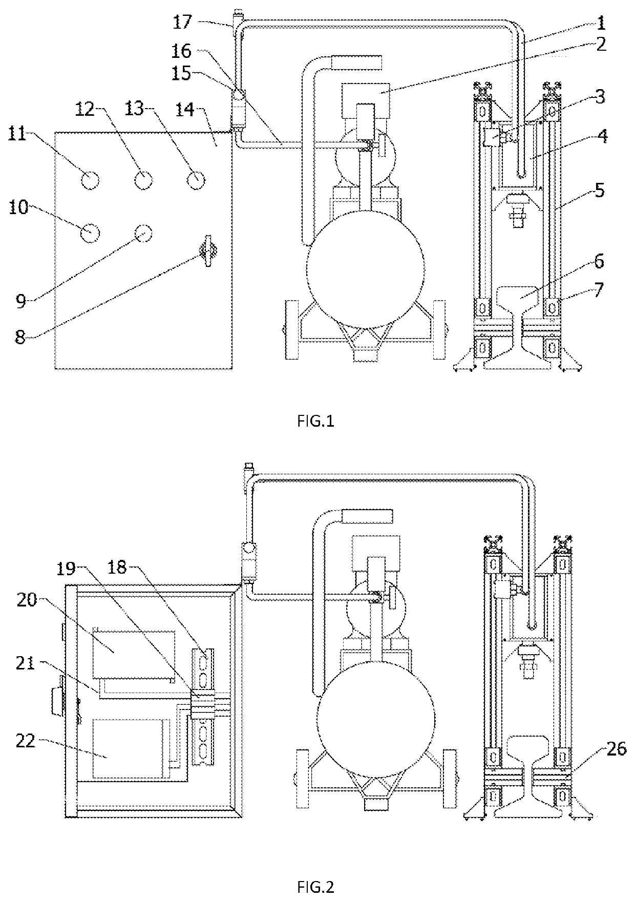
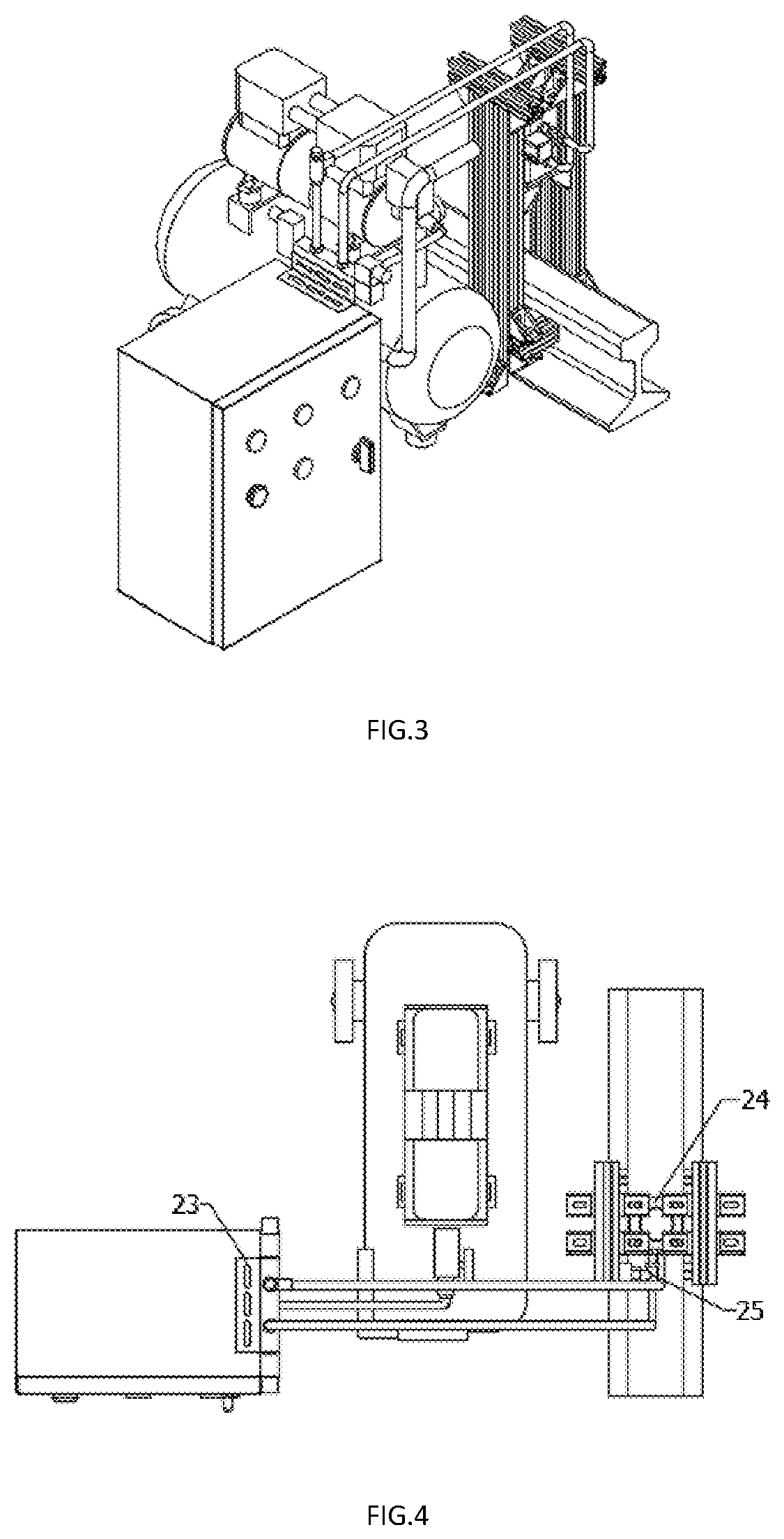
[0027]As shown in FIGS. 1 and 3, a portable pneumatic loading system for simulating the operation of a subway train is provided, including a control cabinet 14, a powered air station 2 and an air cylinder 4. A proportional directional valve 15 is disposed between the control cabinet 14 and the powered air station 2, and the control cabinet 14 is connected to the powered air station 2 through an air inlet pipe 16. The powered air station 2 is connected to the air cylinder 4 through a hose 1. A flow regulating valve 17 is arranged on the air inlet pipe 16.

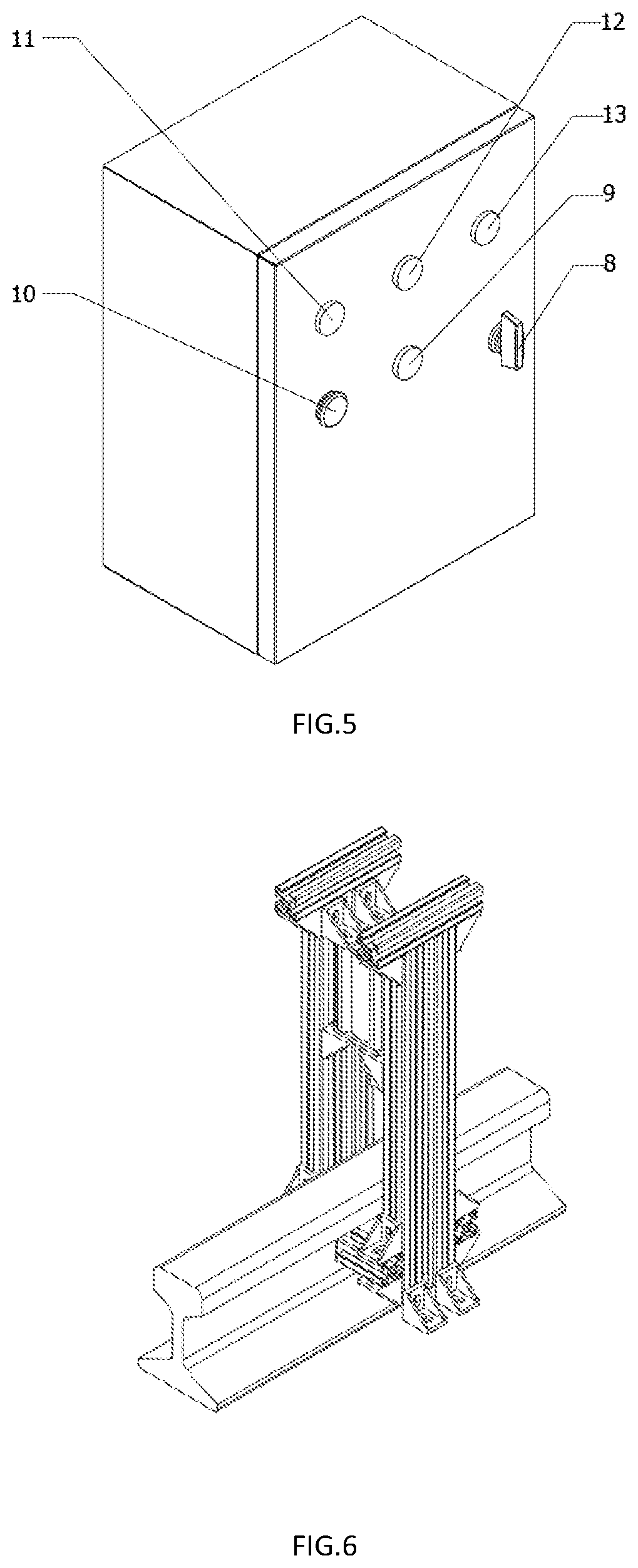
[0028]As shown in FIGS. 1, 2, 3 and 5, a PLC 20, a switching power supply 22 and a guide rail 18 are arranged in the control cabinet 14. The PLC 20 and the switching power supply 22 are connected through signal lines 21 to a wiring terminal 19 fixed on the guide rail 18, respectively. The PLC 20, the sw...


PUM


Abstract

A portable pneumatic loading system for simulating the operation of a subway train is provided, comprising a control cabinet, an powered air station and an air cylinder, wherein a proportional directional valve is disposed between the control cabinet and the powered air station, a control cabinet is connected to the powered air station through an air inlet pipe, and the powered air station is connected to the air cylinder through a hose; a PLC, a switching power supply and a guide rail are arranged in the control cabinet, with the PLC and the switching power supply being connected through signal lines to a wiring terminal fixed on the guide rail; a frequency regulating knob, an emergency stop switch, a main start button, a power start button and a power indicator are embedded in five through holes formed on a door of the control cabinet, respectively; a signal line led out from the top of the control cabinet is connected to the proportional directional valve; and, the air cylinder is connected to the proportional directional valve through a hose. The present invention has the following advantages: the system is light, flexible and portable, and can enter subway tunnels under various working conditions; and, the design is novel and reasonable, the operation is simple, the actual engineering operation is highly feasible, and the on-site adjustment process is more visible.

Description

[0001]This application claims the priority benefit of Chinese Application No. 201910187168.0, filed Mar. 13, 2019 in Chinese, under 35 U.S.C. § 119, which is hereby incorporated by reference.TECHNICAL FIELD OF THE INVENTION[0002]The present invention relates to the technical field of pneumatic vibration loading systems, and in particular to a portable pneumatic loading system for simulating the operation of a subway train.BACKGROUND OF THE INVENTION[0003]To deal with the increasingly prominent traffic jam problem, urban rail transit has been highly appraised as an efficient solution, greatly facilitating residents' life. As one of important facilities for modern urban traffic, the rail transit plays an important role in relieving the traffic pressure on the ground and realizing the sustainable development of urban economy and society, and has become a hotspot for local government investment. Newly-built subway lines in many cities in China will be opened soon. But, how to ensure the...

Claims


Application Information

Patent Timeline
Patent Type & Authority Patents(United States)
IPC IPC(8): G01M7/02B61L23/04
CPCG01M7/022B61L23/04E01B35/12E01B19/00G01M7/00G01M5/0058B61L27/60
Inventor DING, ZHIJIANG, YULU, QIANQIANCHEN, CHENGSHAO, YUANJIZHANG, YINRUIZHU, HONGBINGZHANG, XIAO
Owner ZHEJIANG UNIV CITY COLLEGE
Learn More