Open-face, dual-mode head coil for clinical imaging in ultra-high field MRI scanner

a dual-mode, open-face technology, applied in the direction of magnetic measurement, measurement using nmr, instruments, etc., can solve the problems of inhomogeneous images, inability to reach the target field strength of 7 t, and the availability of ultra-high field mri head coils

Active Publication Date: 2022-08-09
MR COILTECH LTD
View PDF58 Cites 0 Cited by
  • Summary
  • Abstract
  • Description
  • Claims
  • Application Information

AI Technical Summary

Benefits of technology

[0023]A benefit of the invention is to provide an improved head coil apparatus configured for use in an ultra-high field MRI scanner, said head coil apparatus avoiding disadvantages of conventional techniques. In particular, according to a first aspect, the head coil apparatus is to be capable of transmitting RF power with high efficiency, avoiding a claustrophobic effect on the person to be investigated, providing improved brain coverage and / or allowing a direct monitoring of the head of the person to be investigated. According to a second aspect, the head coil apparatus is to be capable of both of sTx and pTx mode operation. Another benefit of the invention is to provide an improved MRI scanner apparatus and an improved method of magnetic resonance imaging of a head of a person to be investigated, avoiding disadvantages of conventional techniques.

Problems solved by technology

It is generally known that a large body coil, installed in the magnet bore of an MRI scanner, is used to apply RF power for spin excitation in conventional clinical MRI scanners operated with main magnetic field strengths of 1.5 T or 3 T. However, this approach is not feasible at a field strength of 7 T, as the excitable Larmor frequency is changed and RF power with shorter wavelengths is required.
Shorter wavelengths create interferences within the extension of the head, so that inhomogeneous images could result.
Despite of the recent progress in development, the available ultra-high field MRI head coils have the following limitations.
Firstly, the head coil can be claustrophobic to patients.
Furthermore, direct patient motion monitoring is impossible during the scan.
However, bite-bars have a limited reliability, and a separate bite-bar is required for each individual.
Another disadvantage of conventional birdcage head coils for sTx mode of the 7 T MRI scanners is limited brain coverage (see FIG. 12A described below).
However, the head coil of [8] is not particularly adapted for an ultra-high field MRI scanner, and it is limited to the use of a distributed-element TEM resonator for RF transmission, which has disadvantages in terms of limited robustness and limited power handling capability.
However, this feature was lost in 7 T MRI scanners because of the need for a local transmit coil and RF shield surrounding the head.
An additional substantial limitation of conventional head coils results from the application of two versions of head coils, using the sTx mode or the pTx mode, resp.
Due to the high costs of each single head coil, substantial costs of the MRI scanner result.

Method used


Image

  • Open-face, dual-mode head coil for clinical imaging in ultra-high field MRI scanner
  • Open-face, dual-mode head coil for clinical imaging in ultra-high field MRI scanner
  • Open-face, dual-mode head coil for clinical imaging in ultra-high field MRI scanner

Examples


first embodiment

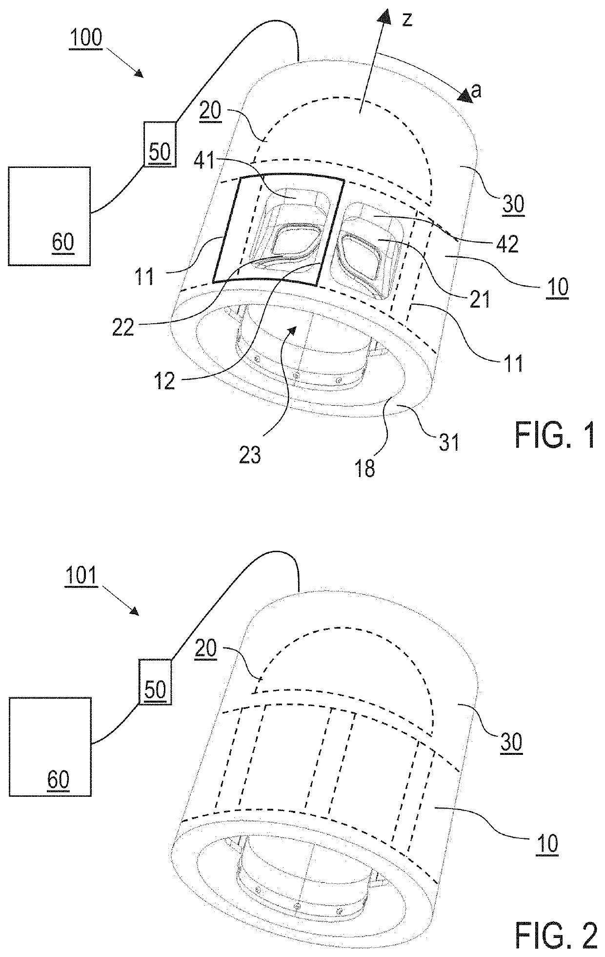
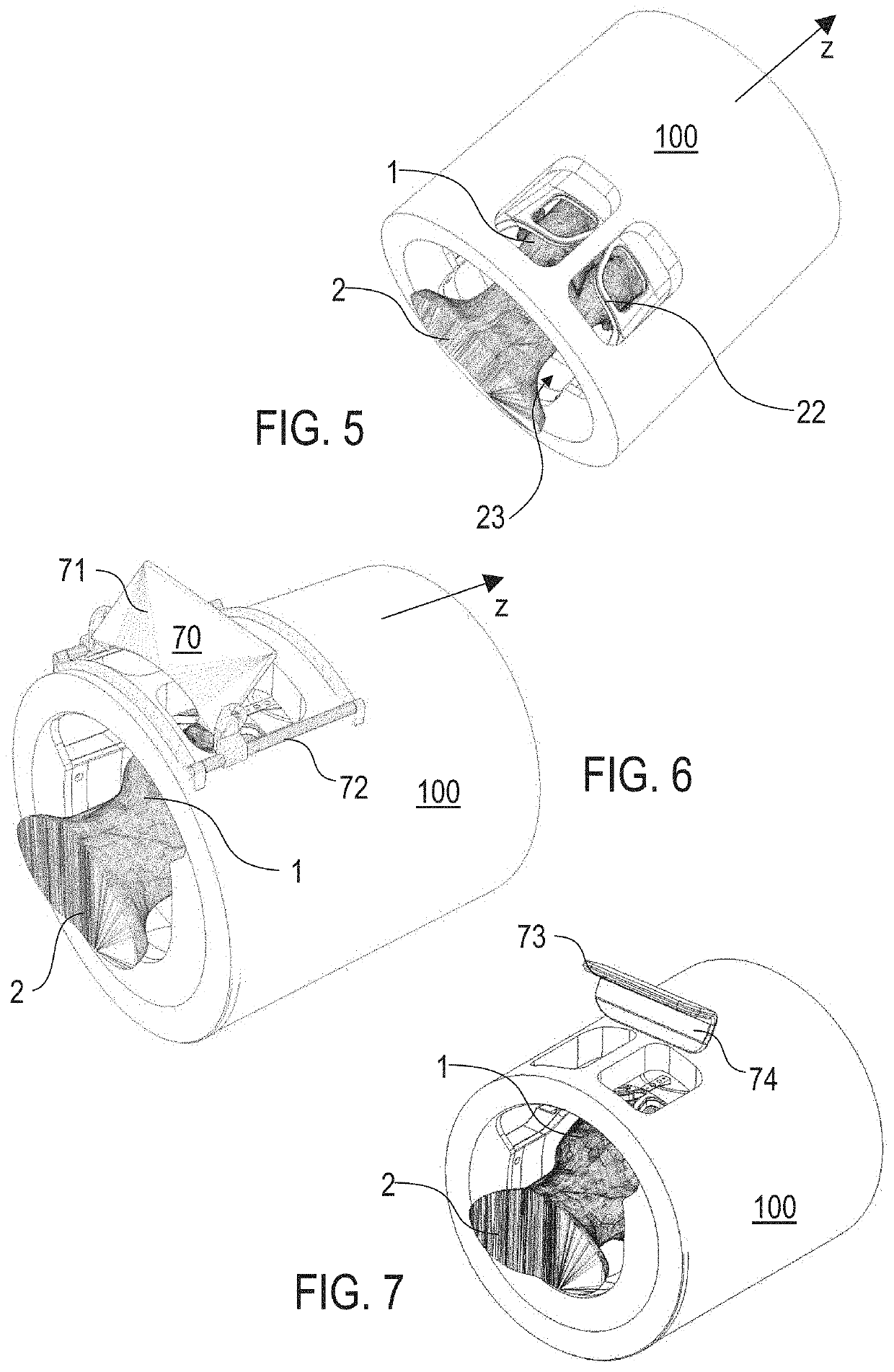
[0060]FIG. 1 shows an outer view of the head coil apparatus 100 for magnetic resonance imaging of a head of a person to be investigated, with a phantom illustration of the transmit coil array device 10 and the receive coil array device 20, which are arranged on a transmit coil array carrier 18 (illustrated by the inner circle) and a helmet-shaped receive coil array carrier 21 (partially shown, see also FIG. 7), resp. The RF shield 30, optionally including an RF shield carrier 31, provides a cylindrical outer enclosure of the head coil apparatus 100. The RF shield can be arranged on an inner or an outer surface of the RF shield carrier 31. The radial distance between the transmit coil array device 10 and the RF shield 30 can range e. g. from 20 mm to 40 mm.

[0061]The head coil apparatus 100 has a longitudinal direction (longitudinal axis, z-axis) which corresponds to the head-feet-axis of the person to be investigated (see e. g. FIGS. 5 and 9). The transmit coil array device 10 has a ...

second embodiment

[0077]Details of the mode splitter device 50 and the operation thereof are described in the following with reference to FIGS. 10 and 11. The mode splitter device 50 can be provided with the first or second embodiment of the inventive head coil apparatus, i. e. in combination with the at least one viewing port or with a closed RF shield / usual transmit coil array. The control device 60 (see FIGS. 1 and 2) includes a number of RF amplifiers corresponding to the number of transmit coil loops of the transmit coil array device, wherein at least one of the RF amplifiers is used for driving the transmit coil array device. The mode splitter device 50 is a switch which can be switched between the single channel mode and the parallel channel mode. Advantageously, the mode splitter device 50 provides a hardware interface and wiring scheme which allows the same head coil apparatus to be used in both the scanner modes. This provides a significant economic benefit to the 7 T MRI customer as they h...


PUM


Abstract

A head coil apparatus for MRI of a person's head includes a transmit coil array device generating RF fields for spin state excitation to the head, wherein the transmit coil array device comprises multiple transmit coil loops decoupled from each other and arranged on a transmit coil array carrier surrounding an inner head coil space for receiving the head; a receive coil array device for receiving RF resonance signals from the head; a RF shield surrounding the transmit coil array device and the receive coil array device; and a head coil window providing a viewing port through the RF shield and transmit coil array device. The head coil window has a longitudinal extension and an azimuthal extension, the transmit coil loops includes a window coil loop surrounding the head coil window, and the coil loop is decoupled from a neighbouring transmit coil loop by sharing a common loop conductor.

Description

BACKGROUND OF THE INVENTIONField of the Invention[0001]The invention relates to a head coil apparatus, being configured for magnetic resonance imaging (MRI) of a human head of a person to be investigated. In particular, the head coil apparatus is configured for use in an ultra-high field MRI scanner, having a magnetic field strength equal to or above 7 T. Furthermore, the invention relates to an MRI scanner apparatus being provided with the head coil apparatus and to a method of magnetic resonance imaging of a head of a person to be investigated. Applications of the invention are available e. g. in the field of clinical head imaging.Technical Background[0002]In the present specification, reference is made to the following prior art illustrating the technical background of the invention, in particular relating to the configuration and operation of ultra-high field MRI scanners:[0003][1] U.S. Pat. No. 7,012,429 B1;[0004][2] U.S. Pat. No. 6,975,114 B1;[0005][3] G. Adriany et al. “Trans...

Claims


Application Information

Patent Timeline
Patent Type & Authority Patents(United States)
IPC IPC(8): G01R33/28G01R33/422G01R33/44
CPCG01R33/283G01R33/422G01R33/445G01R33/34046G01R33/365
Inventor GUNAMONY, SHAJAN
Owner MR COILTECH LTD
Why Eureka
Try Eureka