
Rotary face seal with magnetic puller loading

a magnetic puller and rotary face technology, applied in the direction of engine seals, mechanical apparatus, engine components, etc., can solve the problems of large variation in the loading of the spring mechanism, affecting the service life of the seal, and requiring customer hardware modification, so as to improve the service life and minimize variation. , the effect of improving the sealing performan

Active Publication Date: 2022-09-13
MAGNETIC SEAL LLC
View PDF18 Cites 0 Cited by
  • Summary
  • Abstract
  • Description
  • Claims
  • Application Information

AI Technical Summary

Benefits of technology

[0011]The present invention preserves the advantages of prior art rotary face seals. In addition, it provides new advantages not found in currently available rotary face seals and overcomes many disadvantages of such currently available rotary face seals.
[0012]The invention is generally directed to the novel and unique rotary face seal that has magnetic loading. The rotary face seal with magnetic loading of the present invention replaces the spring mechanism with magnetic technology to provide a consistent load with minimal variation, which is not affected by natural frequency and material fatigue due to cyclic loading. This will improve seal performance and service life by eliminating the issues that compromise the effectiveness of the spring mechanism. The magnetic technology results in a design that uses magnetic technology attached to the outside diameter of the rotary annular ring which is attached to the shaft that does not produce eddy currents because it is of a single pole design. The single pole magnetic assembly design is achieved by either axial or radial magnet orientation. The magnetic pull is preferably provided by a tubular magnetic band.
[0013]It is therefore an object of the present invention to provide improved rotary face seal that overcomes the shortcomings associated with the prior art and provides vastly improved performance compared to such prior art designs.

Problems solved by technology

There are a number of problems and concerns typically associated with known mechanical rotary face seals.
The spring mechanism's loading can have a large variation caused by operating range (stroke) length, compromised when it's natural frequency is reached during operation from shock and vibration, and load reduction (weakening) due to material fatigue under cyclic loading and temperature extremes.
For example, U.S. Pat. No. 3,708,177 for Magnetic Seal for a Rotary Shaft and Magnet Therefor addresses the well-known eddy current issue but it is unknown if the design was commercially feasible.
U.S. Pat. No. 4,795,168 for a Magnetic Seal Assembly does not address the eddy current issue because the magnet inserts rotate.
U.S. Pat. No. 5,078,411 for Variable Magnetic Rotary Seal does not address the eddy current issue because the magnet inserts rotate.
U.S. Pat. No. 5,730,447 for Self-Aligning Magnetic Rotary Seal also does not address the eddy current issue because the magnet inserts rotate.
U.S. Pat. No. 6,805,358 for Magnetic Seal also does not address the eddy current issue because either the magnet inserts rotate or the magnetically attractive member is exposed to continuously changing north and south poles during rotation.
Frictional heat dissipation is achieved due to thermal conductivity.
However, different seal designs for high pressure and pressure reversal require customer hardware modification.
The selection of materials is restricted due to the use of magnetics.
Moreover, there are uncertain production yield rates for magnets that are used.
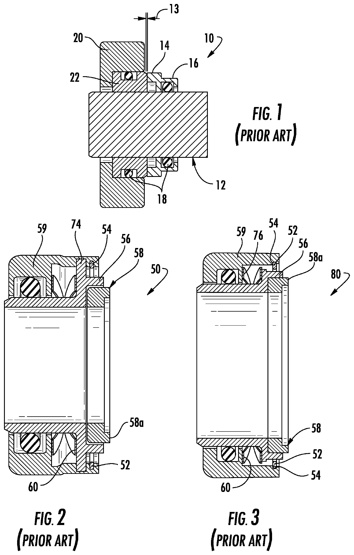
However, the slotted OD design is not practical for all applications with the majority using the internal milled tangs 52 with slots 54 in the seal case 56.
Also, the natural frequency of wave spring 60 is unknown and could cause loading issues under shock and vibration conditions.
These solutions are not enough.

Method used


Image

  • Rotary face seal with magnetic puller loading
  • Rotary face seal with magnetic puller loading
  • Rotary face seal with magnetic puller loading

Examples


Embodiment Construction

[0025]The rotary face seal of the present invention with magnet loading replaces the spring mechanism or a magnet installed in a housing with improved magnetic technology that provides a more consistent load with minimal variation, which is not affected by natural frequency and material fatigue due to cyclic loading. This improves the seal performance and service life by eliminating the issues that compromise the effectiveness of the spring mechanism. The present invention as envisioned uses magnetic technology attached to the outside diameter of the rotary ring which is attached to the shaft. The single pole magnetic assembly design is achieved by either axial or radial magnet orientation. Thus, the tubular and single pole design of the magnet used in the present invention does not produce eddy currents due to its configuration and design.

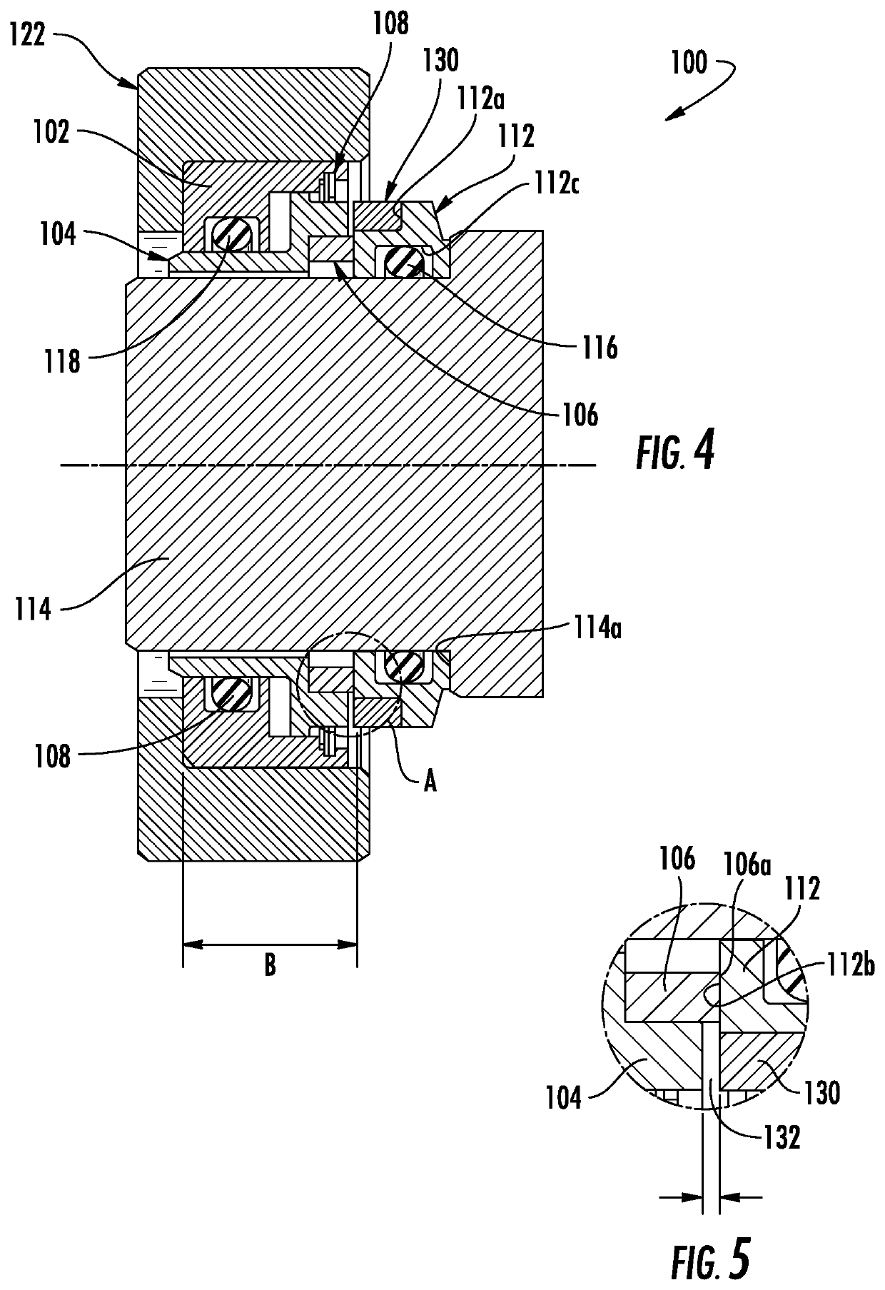
[0026]Referring to FIGS. 4 and 5, which is a close-up view of the gap between the tubular magnet 130 and seal case 104, of the rotary face seal 1...


PUM


Abstract

The rotary face seal with magnet loading replaces known spring mechanisms with magnetic technology that provides a consistent load with minimal variation, which is not affected by natural frequency and material fatigue due to cyclic loading. This improves seal performance and service life. The tubular magnetic ring is advantageous because it replaces existing seals within stationary cartridge with a puller type magnetic assembly design that results with the stationary cartridges being an exact exchange. The use of magnetic technology attached to the outside diameter of the rotating mating ring, which is attached to the shaft, that does not produce eddy currents because it is of a single pole configuration. The single pole magnetic assembly design is achieved by either axial or radial magnet orientation, such as in the form of a tubular magnetic band locating in a circumferential notch in the rotating mating ring.

Description

CROSS REFERENCE TO RELATED APPLICATION[0001]This patent application claims priority to earlier filed U.S. Provisional Application Ser. No. 62 / 362,348, filed Jul. 14, 2016 the entire contents of which are incorporated herein by reference.BACKGROUND OF THE INVENTION[0002]The invention relates generally to mechanical rotary face seals. Such mechanical rotary face seals are typically used to seal media (gas or fluid) between the shaft and the housing where one is stationary and the other is rotating. These seals are used in the aerospace industry, commercial industry, nuclear industry, and other high reliability industries, such as, test equipment and race car engines and transmissions or the like.[0003]There are a number of problems and concerns typically associated with known mechanical rotary face seals. Standard mechanical rotary face seals use a spring mechanism for the mechanical load that provides positive contact against the rotary mating surface that is either a separate ring a...

Claims


Application Information

Patent Timeline
Patent Type & Authority Patents(United States)
IPC IPC(8): F16J15/34F16J15/00F16J15/3252F16J15/3268
CPCF16J15/3436F16J15/002F16J15/3412F16J15/3416F16J15/3444F16J15/3252F16J15/3268F16J15/348
Inventor RYAN, PAUL RICHARD
Owner MAGNETIC SEAL LLC
Learn More