Method for making a flexure bearing mechanism for a mechanical timepiece oscillator

a technology of mechanical oscillators and bearing mechanisms, which is applied in the field of making a flexure bearing mechanism for a mechanical oscillator, can solve the problems that cannot be directly combined with conventional escapement mechanisms, and achieve the effect of high position insensitivity in spa

Active Publication Date: 2022-09-27
THE SWATCH GRP RES & DEVELONMENT LTD
View PDF15 Cites 2 Cited by
  • Summary
  • Abstract
  • Description
  • Claims
  • Application Information

AI Technical Summary

Problems solved by technology

However, flexure pivots generally have a limited angular stroke, of around 10° to 20°, which is very low in comparison to the usual 300° amplitude of a balance / balance spring, and which means they cannot be directly combined with conventional escapement mechanisms, and especially with the usual stopping members such as a Swiss lever or suchlike, which require a large angular stroke to ensure proper operation.

Method used


Image

  • Method for making a flexure bearing mechanism for a mechanical timepiece oscillator
  • Method for making a flexure bearing mechanism for a mechanical timepiece oscillator
  • Method for making a flexure bearing mechanism for a mechanical timepiece oscillator

Examples


Embodiment Construction

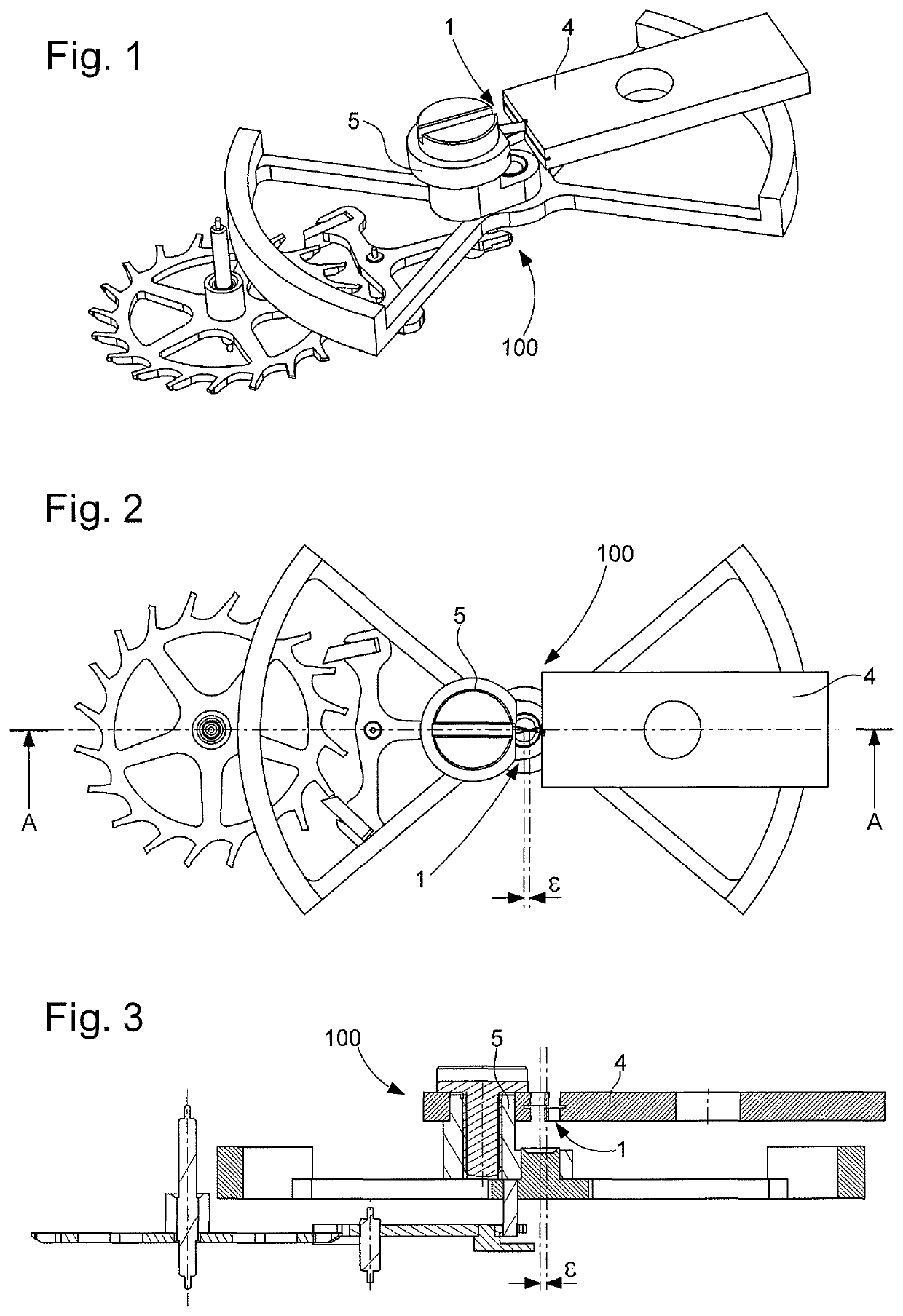
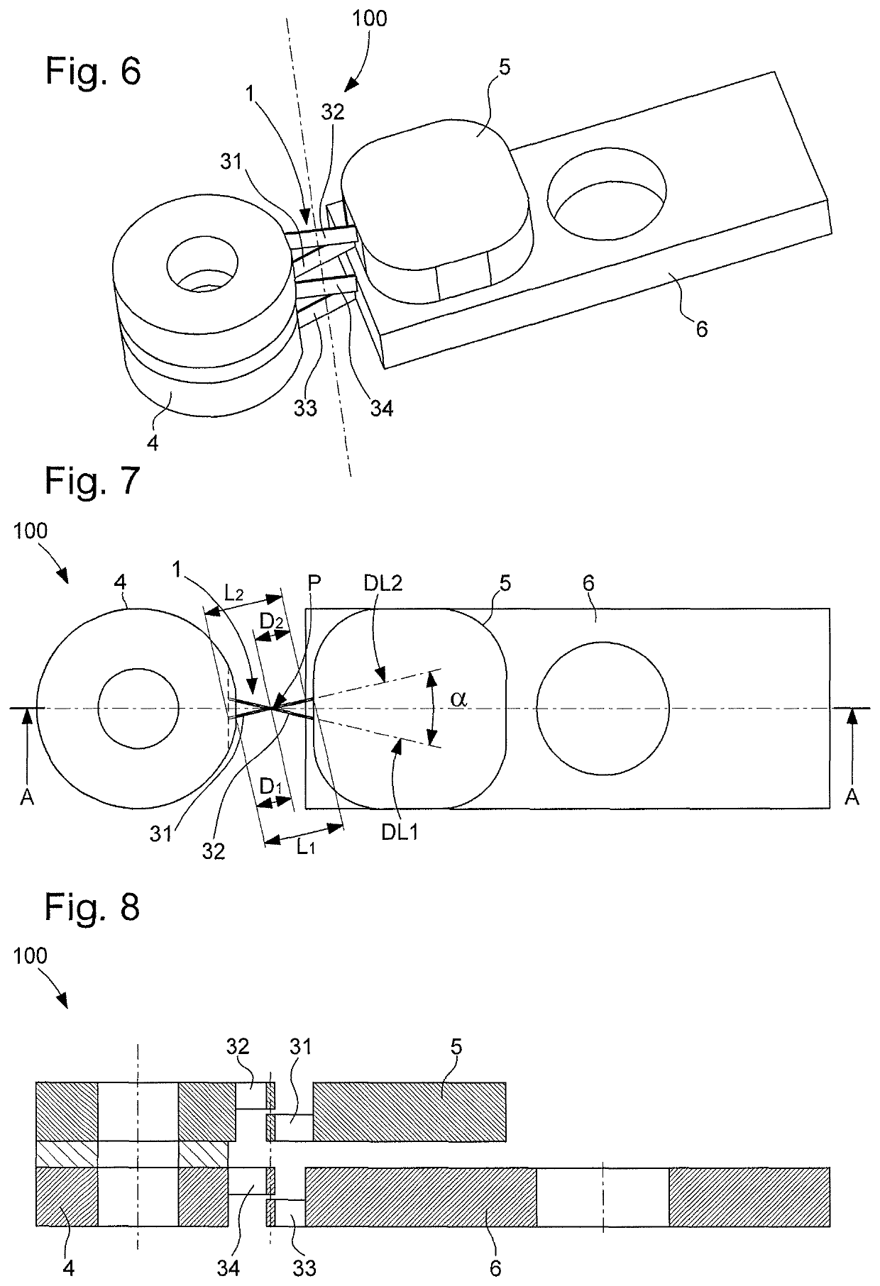
[0049]The invention concerns the making of a mechanical timepiece oscillator 100, comprising at least one rigid support element 4 directly or indirectly fixed to a plate 900, and a solid inertial element 5. This oscillator 100 includes, between rigid support element 4 and solid inertial element 5, a flexure bearing mechanism 200. This flexure bearing mechanism includes at least two first flexible strips 31, 32, which support solid inertial element 5 and are arranged to return it to a rest position. This solid inertial element 5 is arranged to oscillate angularly in an oscillation plane about said rest position.

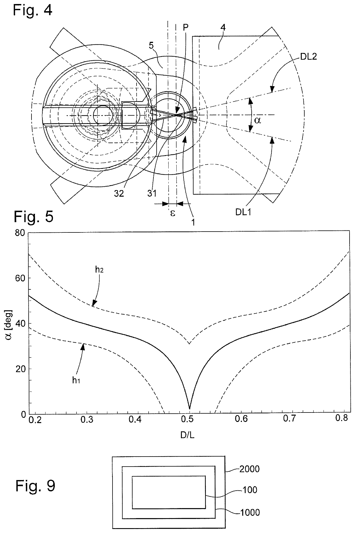
[0050]The two first flexible strips 31 and 32 do not touch each other, and, in the rest position, their projections onto the oscillation plane intersect at a crossing point P, in immediately proximity to which or through which passes the axis of rotation of solid inertial element 5 perpendicularly to the oscillation plane. All the geometric elements described hereinafter shoul...


PUM


Abstract

A method for making a flexure bearing for an oscillator with an inertial element oscillating in a plane supported by flexible strips fixed to a stationary support returning it to a rest position includes: forming the bearing with basic strips in superposed levels, each having an aspect ratio of less than 10; breaking down the number of basic levels into a plurality of sub-units, each including one or two strips joining a basic support and a basic inertial element, which are made by etching substrates; assembling the sub-units by joining their basic inertial elements; and fixing the basic supports to the support, directly or via translational tables along one or two in-plane translational degrees of freedom, of lower translational stiffness than that of the sub-unit.

Description

CROSS-REFERENCE TO RELATED APPLICATION[0001]The present application claims priority to European Patent Application No. 18185139.5, filed on Jul. 24, 2018, the entire content and disclosure of which are incorporated by reference herein.FIELD OF THE INVENTION[0002]The invention concerns a method for making a flexure bearing mechanism for a mechanical oscillator including at least one solid inertial element arranged to oscillate in an oscillation plane, said flexure bearing including at least two first flexible strips which extend in parallel or coincident planes and are each of substantially rectangular cross section and arranged to be fixed to or embedded in a stationary support and to support said solid inertial element, and together arranged to return said inertial element to a rest position.[0003]The invention concerns the field of mechanical oscillators for timepieces comprising flexure bearings with flexible strips performing the functions of holding and returning movable elemen...

Claims


Application Information

Patent Timeline
Patent Type & Authority Patents(United States)
IPC IPC(8): G04B13/02G04B17/04G04B17/32G04B17/26
CPCG04B13/026G04B17/045G04B17/26G04B17/32G04B31/06G04B17/04G04B17/28G04B31/02
Inventor DI DOMENICO, GIANNICUSIN, PIERREHELFER, JEAN-LUCGANDELHMAN, ALEXWINKLER, PASCALHINAUX, BAPTISTELECHOT, DOMINIQUEMATTHEY, OLIVIERKLINGER, LAURENTFAVRE, JEROME
Owner THE SWATCH GRP RES & DEVELONMENT LTD
Why Eureka
Try Eureka