Luminance deblock filtering encoding device, decoding device, and program

a filtering and encoding device technology, applied in the field of encoding devices, decoding devices and programs, can solve the problems of reducing the average error amount of blocks, reducing the effect of deblocking filtering, and reducing the difficulty of deblocking filtering according to the related art to sufficiently so as to reduce the compression efficiency and reduce the distortion of blocks

Active Publication Date: 2022-09-27
NIPPON HOSO KYOKAI
View PDF8 Cites 1 Cited by
  • Summary
  • Abstract
  • Description
  • Claims
  • Application Information

AI Technical Summary

Benefits of technology

[0010]Further, as the quantization parameter becomes excessively small, an average error amount of blocks can be decreased. However, as the quantization parameter becomes small, an action of the deblocking filtering is also reduced, such that it is not possible to sufficiently solve the problem that the difference between the luminance signal levels in a boundary portion is conspicuously presented. In addition, when the quantization parameter becomes small, an amount of information is increased, and thus a compression effect is also reduced.
[0011]In view of the above, an object of the present invention is to provide an encoding device, a decoding device and a program that can reduce block distortion without decreasing compression efficiency.
[0018]According to the present invention, block distortion can be reduced without decreasing compression efficiency.

Problems solved by technology

For this reason, in the case of HDR signal, a non-linearity of a difference between luminance signal levels and a difference between display light levels is high, and it is difficult for the deblocking filtering according to the related art to sufficiently reduce a block distortion.
In addition, even in the case of the SDR signal according to the related art, a non-linearity is caused by gamma correction, and thus an effect of the deblocking filtering is reduced in a region with a high light level, which is problematic.
Further, as the quantization parameter becomes excessively small, an average error amount of blocks can be decreased.
However, as the quantization parameter becomes small, an action of the deblocking filtering is also reduced, such that it is not possible to sufficiently solve the problem that the difference between the luminance signal levels in a boundary portion is conspicuously presented.

Method used


Image

  • Luminance deblock filtering encoding device, decoding device, and program
  • Luminance deblock filtering encoding device, decoding device, and program
  • Luminance deblock filtering encoding device, decoding device, and program

Examples


Embodiment Construction

[0023]Hereinafter, an embodiment of the present invention will be described in detail with reference to the drawings.

(Encoding Device)

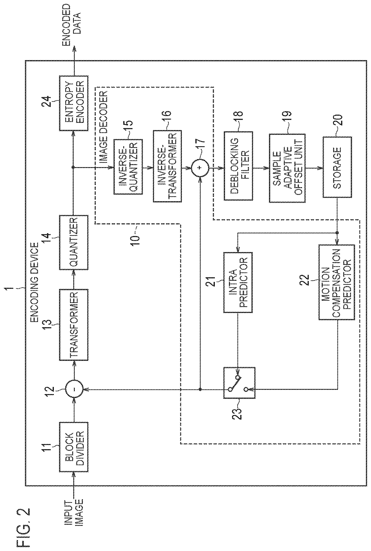
[0024]An encoding device according to an embodiment of the present invention is described below. FIG. 2 illustrates an exemplary configuration of the encoding device according to the embodiment of the invention. The encoding device 1 illustrated in FIG. 2 includes a block divider 11, a subtractor 12, a transformer 13, a quantizer 14, an inverse-quantizer 15, an inverse-transformer 16, an adder 17, a deblocking filter 18, a sample adaptive offset unit 19, a storage 20, an intra predictor 21, a motion compensation predictor 22, a switcher 23, and an entropy encoder 24. It is noted that the sample adaptive offset unit 19 is an optional component. A processing unit that performs another post-filtering process may be provided instead of or in addition to the sample adaptive offset unit 19.

[0025]The block divider 11 divides a frame to be encoded, which is a...


PUM


Abstract

An encoding device 1 includes: a transformer 13 configured to calculate an orthogonal transform coefficient by performing an orthogonal transformation process on a residual image indicating a difference between the input image and a predicted image of the input image; a quantizer 14 configured to generate quantization coefficient by quantizing the orthogonal transform coefficient based on a quantization parameter; an entropy encoder 24 configured to generate encoded data by encoding the quantization coefficient; an image decoder 10 configured to restore an orthogonal transform coefficient from the quantization coefficient based on the quantization parameter and generate a pre-filtering image by adding the predicted image to a residual image restored by performing inverse orthogonal transformation on the orthogonal transform coefficient; and a deblocking filter 18 configured to perform a filtering process on the pre-filtering image and control a filtering strength depending on a result of comparison between a luminance signal level of the pre-filtering image and a luminance threshold value.

Description

RELATED APPLICATIONS[0001]The present application is a continuation based on PCT Application No. PCT / JP2019 / 041254, filed on Oct. 21, 2019, which claims the benefit of Japanese Patent Application No. 2018-198728 filed on Oct. 22, 2018. The content of which is incorporated by reference herein in their entirety.TECHNICAL FIELD[0002]The present invention relates to an encoding device, a decoding device and a program for performing a deblocking filtering process.BACKGROUND ART[0003]In a video encoding method represented by moving picture experts group (MPEG) which has been mainstream, for convenience in realizing real time processing, encoding (compression) is performed by using a technology of dividing a unit of a video which is called a frame (or a picture) or the like into small regions in a block form and performing transformation in a block unit, prediction, or the like. In such an encoding method, a quality difference in a block boundary caused by a difference between neighboring ...

Claims


Application Information

Patent Timeline
Patent Type & Authority Patents(United States)
IPC IPC(8): H04N19/60H04N19/117H04N19/124H04N19/172H04N19/91
CPCH04N19/60H04N19/117H04N19/124H04N19/172H04N19/91H04N19/82H04N19/136H04N19/86
Inventor ICHIGAYA, ATSUROIWAMURA, SHUNSUKENEMOTO, SHIMPEIIGUCHI, KAZUHISA
Owner NIPPON HOSO KYOKAI
Why Eureka
Try Eureka