
Steering control device

a technology of steering control and control characteristics, which is applied in the direction of steering control, electric steering, vehicle components, etc., can solve the problems of difficulty in achieving the control characteristics appropriate to the steering control function, and achieve the effect of both control characteristics

Active Publication Date: 2022-11-01
JTEKT CORP
View PDF7 Cites 2 Cited by
  • Summary
  • Abstract
  • Description
  • Claims
  • Application Information

AI Technical Summary

Benefits of technology

[0007]A control device of a so-called steer-by-wire type steering apparatus, in which dynamic force transmission between a steering wheel and turning wheels is isolated, has also the same problem as the control device of the EPS. The present disclosure provides a steering control device that makes it possible to obtain a more appropriate control characteristic depending on the control content.
[0015]With the steering control device according to the aspect of the present disclosure, since the control parameter for the controller is altered depending on the purpose of the intervention in the steering control by the host control device, the responsiveness of at least one of the feedback control for the electric current that is supplied to the turning motor and the feedback control for the rotation angle of the shaft that rotates depending on the turning action of the turning wheel is altered. Therefore, it is possible to obtain a more appropriate responsiveness depending on the purpose of the intervention by the host control device, as the responsiveness of the feedback control for at least one of the electric current that is supplied to the turning motor and the rotation angle of the shaft that rotates depending on the turning action of the turning wheel. Furthermore, it is possible to obtain a more appropriate turning control characteristic depending on the purpose of the intervention by the host control device.

Problems solved by technology

Therefore, for example, in the case where the control device of the EPS has a steering control function requiring the responsiveness and a steering control function requiring the silence, it is difficult to achieve both of control characteristics appropriate to the steering control functions.
A control device of a so-called steer-by-wire type steering apparatus, in which dynamic force transmission between a steering wheel and turning wheels is isolated, has also the same problem as the control device of the EPS.

Method used


Image

  • Steering control device
  • Steering control device
  • Steering control device

Examples


first embodiment

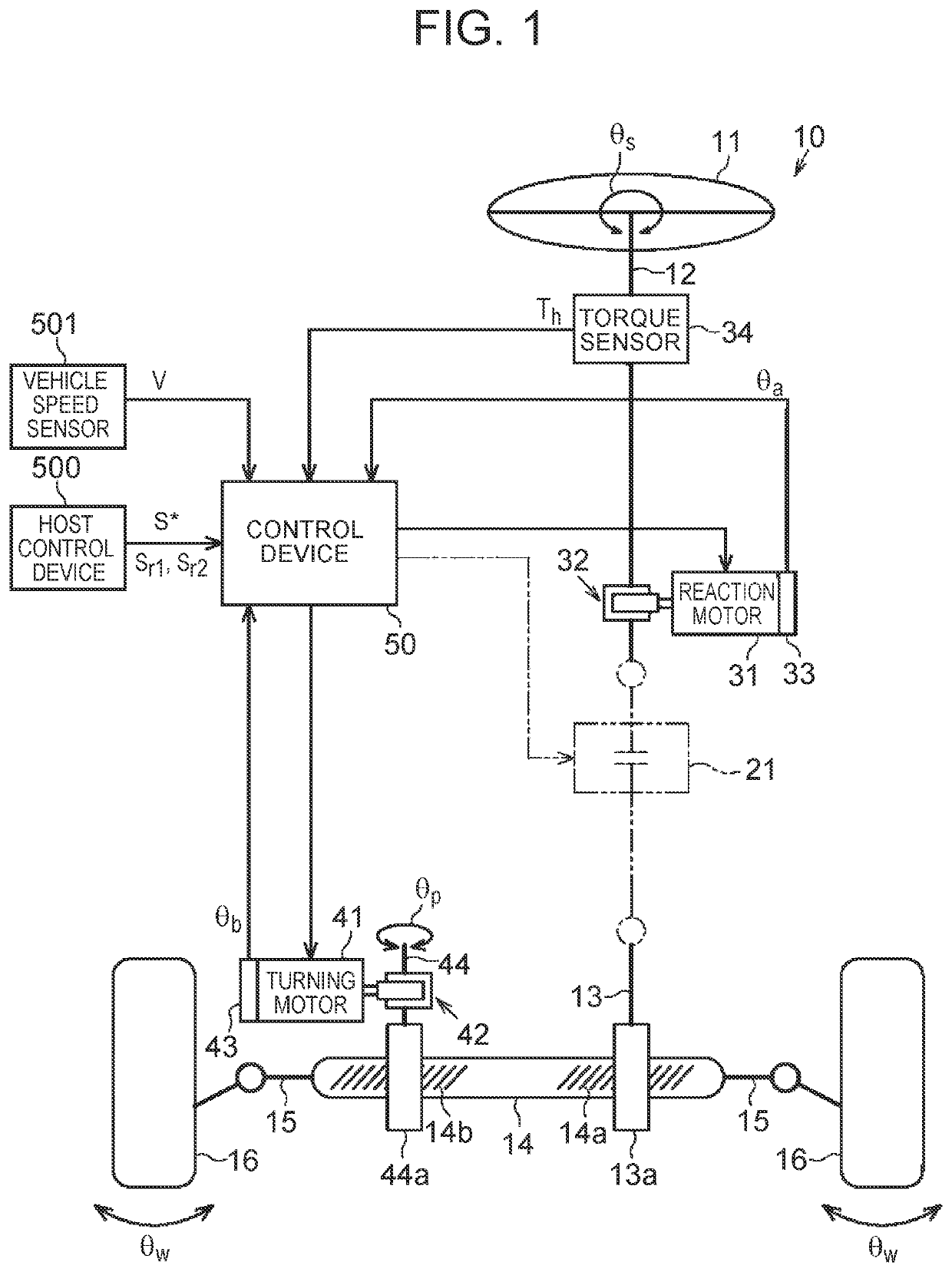
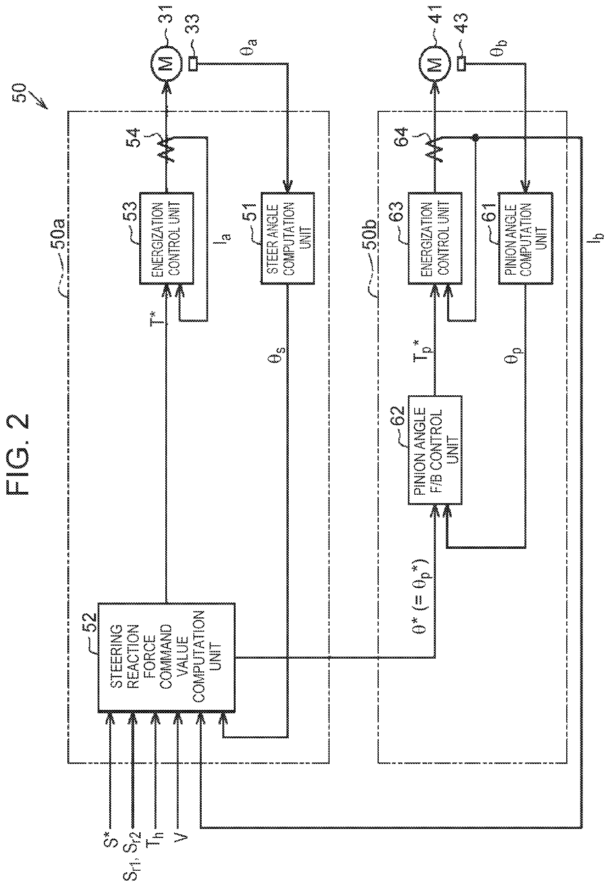
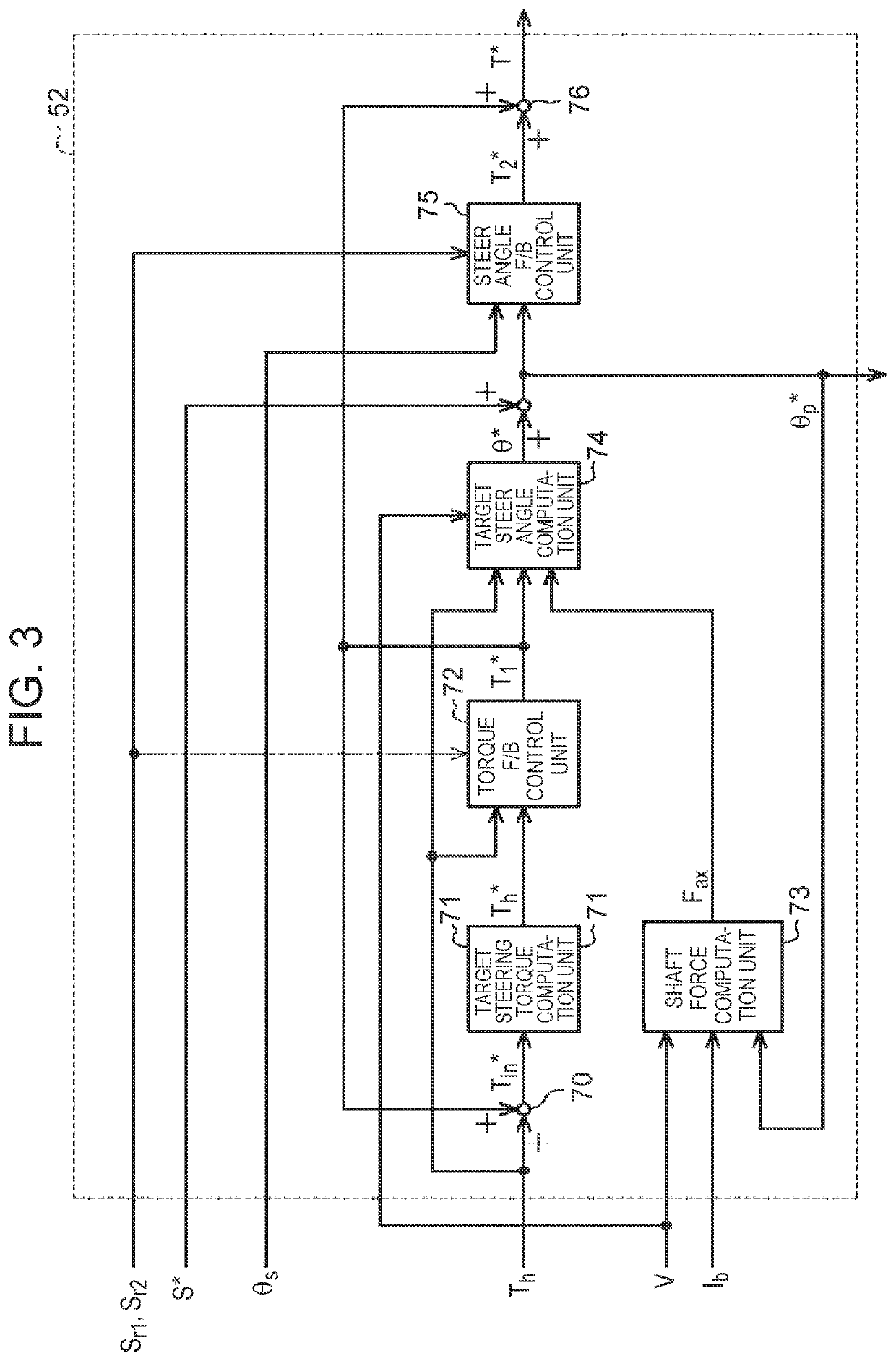
[0032]A first embodiment in which a steering control device is applied to a steer-by-wire type steering apparatus will be described below.

[0033]As shown in FIG. 1, a steering apparatus 10 of a vehicle includes a steering shaft 12 that is coupled to a steering wheel 11. The steering shaft 12 constitutes a steering mechanism. Further, the steering apparatus 10 includes a turning shaft 14 that extends along a vehicle width direction (a right-left direction in FIG. 1). Right and left turning wheels 16 are coupled to both ends of the turning shaft 14 through tie rods 15, respectively. A turning angle θw of the turning wheels 16 is altered by linear motion of the turning shaft 14.

[0034]Configuration for Generating Steering Reaction Force: Reaction Unit

[0035]The steering apparatus 10 includes a reaction motor 31, a speed reducer 32, a rotation angle sensor 33 and a torque sensor 34, as a configuration for generating a steering reaction force. Incidentally, the steering reaction force is a ...

second embodiment

[0099]Next, a second embodiment of the steering control device will be described. The embodiment is different from the first embodiment in the configuration of the steer angle feedback control unit 75 (proportional controller).

[0100]As shown in FIG. 5, the steer angle feedback control unit 75 includes a single gain computation unit 88, in addition to the subtractor 81 and the two multipliers 86, 87. Each of the two gradual-change processing units 82, 83 and the gain computation units 84, 85 shown in FIG. 4 is excluded.

[0101]The gain computation unit 88 includes table data 88a. The gain computation unit 88 computes a gain G3 by referring to the table data 88a. The table data 88a is information specifying a correspondence relation between the values (“1” or “0”) of the commands Sr1, Sr2 and the gain G3. The gain computation unit 88 sets the value of the gain G3 depending on the values of the commands Sr1, Sr2. Details are shown as follows.

[0102]When the value of the flag as the comman...

third embodiment

[0107]Next, a third embodiment of the steering control device will be described. The embodiment is different from the first embodiment in the configuration of the torque feedback control unit 72.

[0108]The torque feedback control unit 72 has the same configuration as the steer angle feedback control unit 75 shown in FIG. 4. As shown by reference characters in parentheses in FIG. 4, the torque feedback control unit 72 takes in the commands Sr1, Sr2 generated by the host control device 500, and adjusts the proportional gain Kp depending on the taken commands Sr1, Sr2.

[0109]While the steer angle feedback control unit 75 takes in the target steer angle θ* and the steer angle θs, the torque feedback control unit 72 takes in the steering torque Th and the target steering torque Th* computed by the target steering torque computation unit 71. Further, while the subtractor 81 of the steer angle feedback control unit 75 computes the difference δθ between the target steer angle θ* and the steer...


PUM


Abstract

A steering control device is configured to control a motor, the motor being a generation source of a driving force that is given to a steering mechanism of a vehicle. The steering control device includes a controller configured to compute a controlled variable depending on a steering state, the controlled variable being used in the control of the motor. The controller is configured to alter a control parameter for the controller, based on a command that is generated by a host control device depending on a purpose of an intervention in a steering control, the host control device being mounted on the vehicle.

Description

CROSS-REFERENCE TO RELATED APPLICATION[0001]This application claims priority to Japanese Patent Application No. 2019-076809 filed on Apr. 15, 2019, incorporated herein by reference in its entirety.BACKGROUND1. Technical Field[0002]The present disclosure relates to a steering control device.2. Description of Related Art[0003]There is an electric power steering apparatus (EPS) that gives the torque of a motor, as an assist force, to a steering mechanism of a vehicle. In recent years, there has been actively performed development of an automatic driving system that realizes various driving assist functions for improving safety or convenience of the vehicle or an automatic driving function by which the system performs driving instead of a driver. A control device of the automatic driving system evaluates an optimal control method based on the state of the vehicle at that time, and commands control devices of in-vehicle systems to perform individual controls depending on the evaluated co...

Claims


Application Information

Patent Timeline
Patent Type & Authority Patents(United States)
IPC IPC(8): B62D5/04B62D5/00
CPCB62D5/0463B62D5/005B62D5/0418B62D5/046B62D6/007B62D15/025B62D6/008B62D1/286B62D15/027
Inventor KODERA, TAKASHI
Owner JTEKT CORP
Learn More