Vacuum capacitor

a capacitor and vacuum technology, applied in the field of vacuum capacitors, can solve the problems of limiting the operating reducing the problem, and reducing the problem of the strength ultimately limiting the operation voltage of the capacitor,

Active Publication Date: 2022-11-01
COMET AG
View PDF11 Cites 0 Cited by
  • Summary
  • Abstract
  • Description
  • Claims
  • Application Information

AI Technical Summary

Benefits of technology

[0016]An element of the present invention is in particular to propose a vacuum capacitor comprising a protection means that permits at the same time to reduce the risk of corona discharge between the capacitor and a component placed nearby and to reduce the risk of mechanical damages of the vacuum enclosure of the capacitor.
[0034]In a further preferred embodiment of the present invention, the capacitor is a variable vacuum capacitor or a fixed vacuum capacitor. A variable capacitor has the advantage that its capacitance can be adjusted by adapting the distance between the electrodes or extent of the overlap of the electrode surfaces inside the vacuum dielectric medium.

Problems solved by technology

The field strength ultimately limits the operating voltage of the capacitor for a given electrode separation.
Nowadays, this problem has been greatly diminished and the limiting factor is often the breakdown between the capacitor and the components around it.
This is particularly a problem when the power density must be increased and the impedance matching boxes or other power delivery equipment must remain at the same physical dimensions.
This is problematic since at the protrusions of these steps, a very high electric field is thus generated.
Hence, an unwanted discharge between a vacuum capacitor and a component nearby can happen between these protruding edges and these components.
These bulk or shaped metallic corona rings known in the art are heavy, expensive to manufacture and above all not flexible, which leads to problems when mounting them on the edge of the vacuum capacitors enclosure.
The corona means of these and other prior-art vacuum capacitors are entirely metallic which does not permit to protect the capacitor from mechanical damages besides protecting it from damages due to corona-discharge processes.
The protections means, which are arranged inside such an enclosure, do not prevent damages due to mechanical shocks with an object outside of the vacuum and must be made out a material which is vacuum compatible.
While the form of the cylindric wall can help to prevent corona-discharge, it cannot prevent mechanical damages.

Method used


Image

  • Vacuum capacitor
  • Vacuum capacitor
  • Vacuum capacitor

Examples


Embodiment Construction

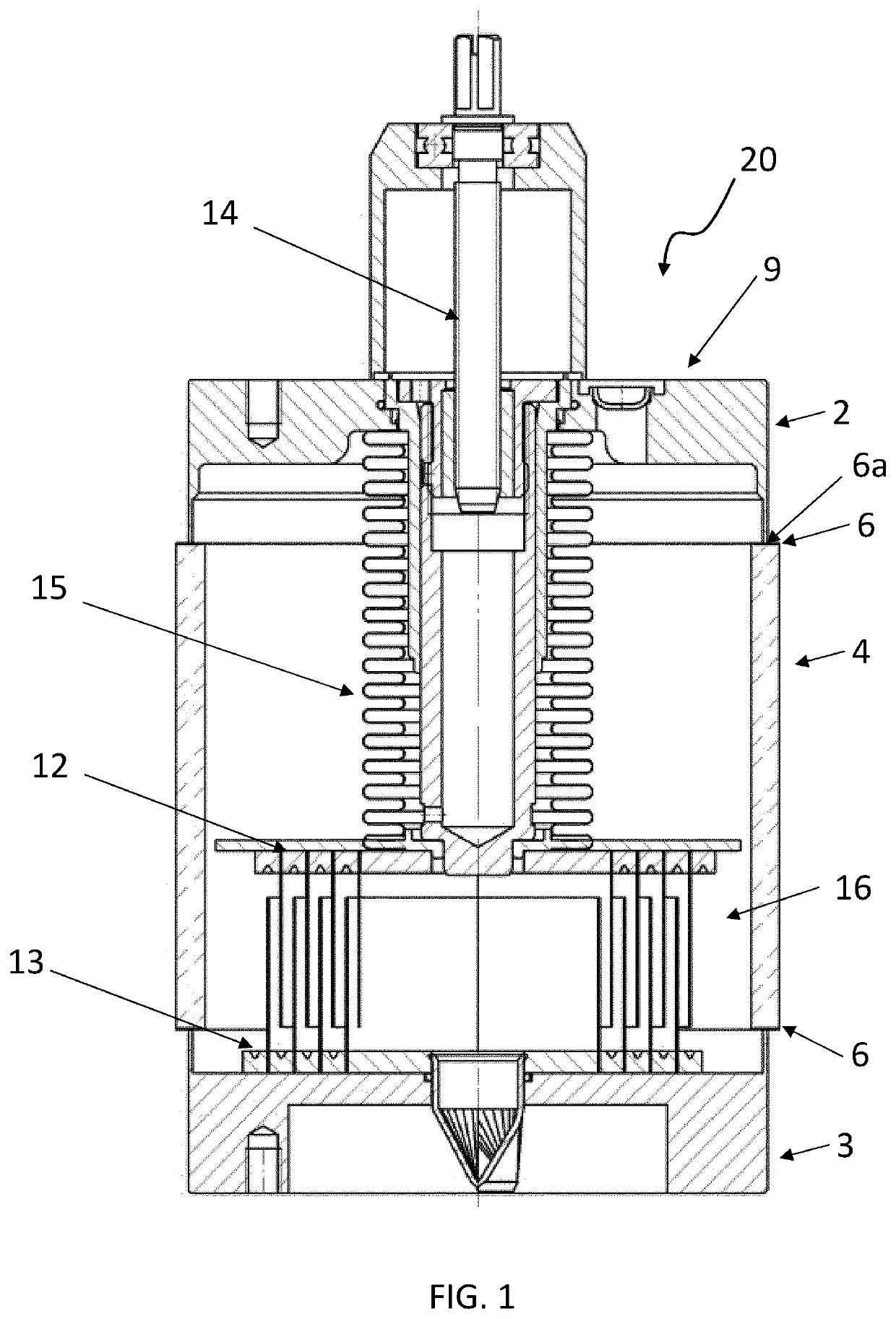
[0040]FIG. 1 shows a section view of a state-of-the-art vacuum capacitor 20. Such a vacuum capacitor comprises an enclosure 9 to contain a vacuum dielectric medium 16; the enclosure comprising a first conductive collar 2 and a second conductive collar 3 (here in the form of metallic collars) separated by an insulating element 4 of the enclosure 9. Commonly the insulating element 4 is made out of a ceramic material in the shape of a cylinder. Due to the manufacturing process and especially due to the requirement associated with the joining, for instance by brazing the insulating element 4 to the metallic collars 2, 3, the insulating element 4 extends further in the radial direction than the collars. Therefore, the insulating element 4 exhibits at least one, in case of FIG. 1 two protruding edges 6. As mentioned, insulating element 4 must be bound to the collars 2, 3, so that the surface of insulating element 4 perpendicular to the collar is eventually covered with a brazing material ...


PUM

PropertyMeasurementUnit
angleaaaaaaaaaa
radio-frequency aaaaaaaaaa

Abstract

The present invention relates to a vacuum capacitor (1, 30) comprising an enclosure (9) to contain a vacuum dielectric medium, a first electrode (12) and a second electrode (13) separated by said vacuum dielectric medium, the enclosure (9) comprising a first conductive collar (2) in electrical contact with the first electrode (12) and a second conductive collar (3) in electrical contact with the second electrode (13), the first conductive collar (2) and the second conductive collar (3) being separated by an insulating element (4) of the enclosure (9), wherein the enclosure (9) exhibits at least one protruding edge (6), said protruding edge (6) being in electrical contact with the closest of the first conductive collar (2) or the second conductive collar (3), wherein the vacuum capacitor (1, 30) comprises at least one protection means (7, 37) covering on the outside of the vacuum enclosure the protruding edge (6), wherein the protection means (7, 37) is made at least partially of an elastomer, wherein at least the outer surface (7b, 37b) of the protection means (7, 37) is electrically conductive and is at the same electrical potential as the closest conductive collar to the protruding edge (6), and wherein the outer surface (7b, 37b) of the protection means (7, 37) has a radius of curvature greater than the radius of curvature of the protruding edge (6).

Description

TECHNICAL FIELD[0001]The present invention relates to the field of vacuum capacitors. More precisely, the present invention relates to a vacuum capacitor comprising a protection means that prevents electrical discharges between protrusions of the enclosure of the vacuum capacitor and nearby components. The protection means are, furthermore, arranged such that the vacuum enclosure of the capacitor are protected against mechanical shocks thereby preventing deformation or damage of the enclosure during transport or subsequently in harsh operational environments.BACKGROUND OF THE INVENTION[0002]Vacuum capacitors are well known in the prior art and are used in applications where both high frequencies and high power are required. Common applications include, for example, oscillation circuits for use in high power radio frequency transmission, and high frequency power supplies for use in manufacturing semiconductors, solar panels and flat panel displays.[0003]Capacitors comprise two or mor...

Claims


Application Information

Patent Timeline
Patent Type & Authority Patents(United States)
IPC IPC(8): H01G5/013H01G5/014H01G5/011H01G5/00
CPCH01G5/013H01G5/011H01G5/014H01G2005/02H01G4/002H01G4/224H01G4/005H01G5/01H01G5/14H01G5/00
Inventor BIGLER, WALTER
Owner COMET AG
Why Eureka
Try Eureka