Inductive sensing system for sensing electromagnetic signals from a body

Active Publication Date: 2022-11-08
KONINKLJIJKE PHILIPS NV
View PDF6 Cites 0 Cited by
  • Summary
  • Abstract
  • Description
  • Claims
  • Application Information

AI Technical Summary

Benefits of technology

[0022]More particularly, research has found that at values of {circumflex over (ω)} below 0.025, the signal to noise ratio of the sensed electromagnetic signal is significantly reduced, leading to higher motion sensitivity. More particularly, below this level, the signal strength is much decreased, and in most practical applications saturated by noise emanating from electronic noise, electromagnetic interference and noise from capacitive coupling with the surface of the body (i.e. direct coupling via electric fields and electrically induced charges).
[0071]Applying excitation signals to a body at such high frequencies is not known in the prior art. This is because it is commonly understood in the art that frequencies above around 30 MHz lead to significant reduction in achievable penetration depth, while increasing the required operating power. However, inventors of the present invention have found that the reduction in penetration depth does not become prohibitive to inductive sensing (in particular for physiological parameter sensing) until much larger frequencies are reached. This is particularly the case in applications pertaining to investigating breathing function. These embodiments hence improve signal strength, and with no prohibitive reduction in penetration depth.

Problems solved by technology

The ongoing research however has never led to adoption of the technology in commercial applications, since the signals achieved from inductive sensors remain notoriously weak, and often saturated by noise.
In state of the art systems, signal strength remains prohibitively low, preventing the technology from being usefully applied in commercial applications.

Method used


Image

  • Inductive sensing system for sensing electromagnetic signals from a body
  • Inductive sensing system for sensing electromagnetic signals from a body
  • Inductive sensing system for sensing electromagnetic signals from a body

Examples


Embodiment Construction

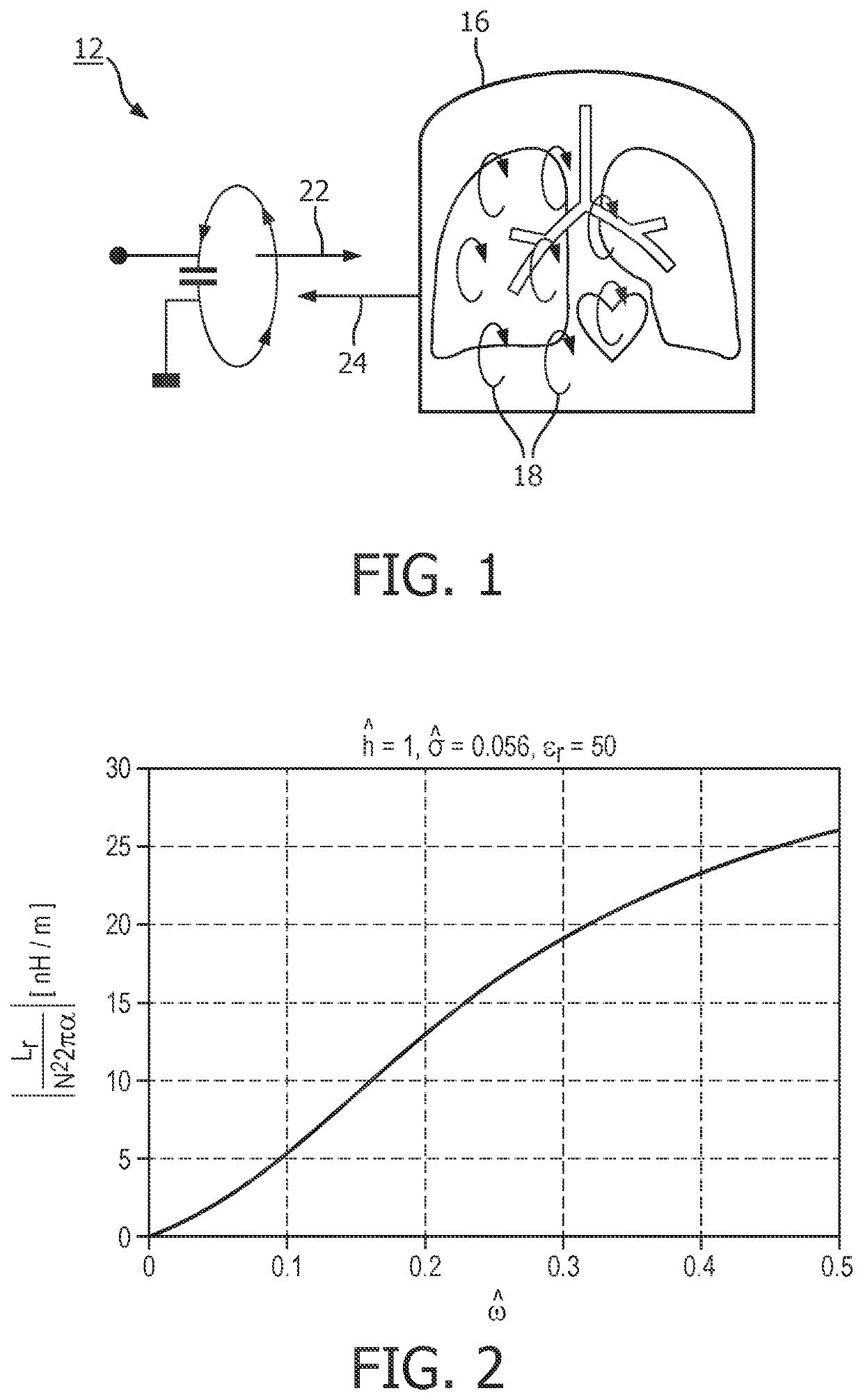
[0112]The invention provides a magnetic inductive sensing system for sensing electromagnetic signals emitted from a body in response to electromagnetic excitation signals applied to the body. The electromagnetic signals are generated and sensed by the same loop resonator which comprises a single-turn loop antenna and a tuning capacitor. The loop antenna of the resonator and a signal generation means for exciting the resonator to generate excitation signals are together configured so as to optimize the value of a ratio between the radial frequency of the generated electromagnetic excitation signals and a reference frequency of the antenna, where the reference frequency is the frequency for which one wavelength of the generated excitation signals (waves) matches the circumferential length of the antenna. This ratio, which corresponds to a normalized radial frequency of the generated excitation signals, is maintained between a value of 0.025 and 0.50.

[0113]The invention is based on res...


PUM


Abstract

The invention provides a magnetic inductive sensing system for sensing electromagnetic signals emitted from a body in response to electromagnetic excitation signals applied to the body. The electromagnetic signals are generated and sensed by the same loop resonator which comprises a single-turn loop antenna and a tuning capacitor. The loop antenna of the resonator and a signal generation means for exciting the resonator to generate excitation signals are together configured so as to optimize the value of a ratio between the radial frequency of the generated electromagnetic excitation signals and a reference frequency of the antenna, where the reference frequency is the frequency for which one wavelength of the generated excitation signals (waves) matches the circumferential length of the antenna. This ratio, which corresponds to a normalized radial frequency of the generated excitation signals, is maintained between a value of 0.025 and 0.50.

Description

CROSS-REFERENCE TO PRIOR APPLICATIONS[0001]This application is the U.S. National Phase application under 35 U.S.C. § 371 of International Application No. PCT / EP2018 / 050044, filed on 2 Jan. 2018, which claims the benefit of European Patent Application No. 17150641.3, filed on 9 Jan. 2017 and European Patent Application No. 17169584.4, filed 4 May 2017. These applications are hereby incorporated by reference herein.FIELD OF THE INVENTION[0002]This invention relates to an inductive sensing system for sensing electromagnetic signals from a body, and in particular a sensor for inductively coupling with a body for sensing electromagnetic signals.BACKGROUND OF THE INVENTION[0003]Inductive sensing can be used as a means of non-invasive investigation of properties of a body.[0004]In one advantageous area of application, inductive sensing can be used as a means of non-invasively investigating physiological characteristics, in particular heart and lung dynamics. Inductive sensing is based on m...

Claims


Application Information

Patent Timeline
Patent Type & Authority Patents(United States)
IPC IPC(8): A61B5/0265A61B5/00A61B7/00
CPCA61B5/0265A61B5/7225A61B7/003A61B2560/0462A61B2562/166A61B2562/182A61B2562/222A61B5/05A61B2562/0223
Inventor PEETERS, WOUTER HERMANKLEIJNEN, MARK PETER PAULDOODEMAN, GERARDUS JOHANNES NICOLAASBEZEMER, RICKLEIJSSEN, JACOBUS JOSEPHUSGROSFELD, RONNY HUBERTUS JOHANNES
Owner KONINKLJIJKE PHILIPS NV
Why Eureka
Try Eureka