Instrumented coupling electronics

a technology of instrumented couplings and coupling parts, applied in the direction of drilling casings, drilling pipes, surveying, etc., can solve the problems of substantial cost and subject to damage, and achieve the effects of reducing manufacturing costs, saving rotor assembly, and increasing productivity

Active Publication Date: 2022-11-22
BAKER HUGHES OILFIELD OPERATIONS LLC
View PDF11 Cites 1 Cited by
  • Summary
  • Abstract
  • Description
  • Claims
  • Application Information

AI Technical Summary

Benefits of technology

[0008]The cavities within the carrier wall may be positioned at circumferentially displaced locations around the carrier, so that the elongated sensors are side-by-side within the carrier wall. The carrier may therefore be shorter than a conventional carrier, in which the components of each sensor assembly (e.g., sensor, electronics, manifold) are positioned end-to-end in a tubular housing. Since the carrier itself serves as the sensor housing, the material of the conventional sensor housing can be eliminated, and the overall amount of material which is required for the coupling (carrier and sensor packages) is reduced.
[0011]Embodiments disclosed herein may provide a number of advantages over prior art systems and methods. For example, proposed approaches for assembling rotors and subsequently magnetizing the assembled rotors allow for safer rotor assembly and higher productivity with respect to the manufacture of the rotors, which reduces manufacturing costs associated with permanent magnet motors. The disclosed embodiments also enable the magnetization of assembled rotors in the field, including magnetizing rotors that have become demagnetized in the course of operation in the field.

Problems solved by technology

There are a number of disadvantages to the conventional construction of these gauge packages.
For example, a typical gauge package may be several feet long, and may therefore require a substantial amount of material to form the mandrel, which incurs substantial cost.
This housing may also provide some protection for these components, as the sensor package is installed in a somewhat exposed location on the exterior of the mandrel and may therefore be subject to damage as the gauge package is installed or used in the well.
Another disadvantage is that, if the sensor is intended to measure conditions within the bore of the mandrel, a port must be drilled from the exterior pocket to the bore at the interior of the mandrel, and a manifold at the end of the housing of the sensor package must be mounted over this port and sealed.

Method used


Image

  • Instrumented coupling electronics
  • Instrumented coupling electronics
  • Instrumented coupling electronics

Examples


Embodiment Construction

[0021]One or more embodiments of the invention are described below. It should be noted that these and any other embodiments described below are exemplary and are intended to be illustrative of the invention rather than limiting.

[0022]This disclosure is directed to an improved instrumented coupling or gauge package that uses a carrier which serves as a housing for sensors and associated electronics that are installed in pockets or cavities within the carrier wall. The carrier may have an offset bore, so that the carrier wall is thicker on one side, allowing larger cavities to be provided for the sensors and electronics.

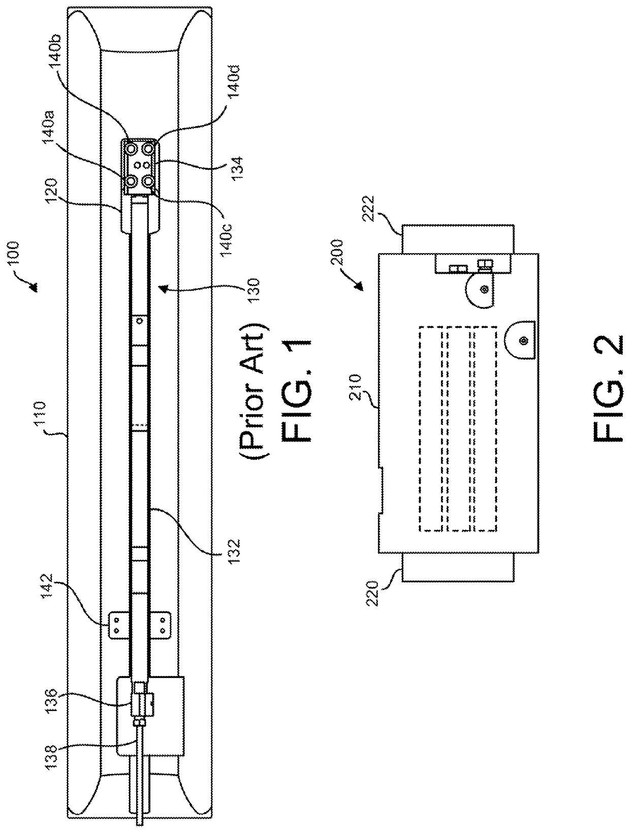
[0023]Referring to FIGS. 1 and 2, diagrams illustrating differences between a conventional gauge package and an improved gauge package (an instrumented coupling) in accordance with one embodiment of the invention are shown. As depicted in FIG. 1, the conventional gauge package 100 is constructed using an elongated tubular mandrel 110 which serves as a carrier. A coupli...


PUM


Abstract

An compact instrumented downhole coupling that includes a carrier and a set of sensors and electronics that are installed within the carrier. The carrier is a tubular structure having couplings at each end and a bore extending through the carrier from the first end to the second end, forming a carrier wall between the bore and the exterior surface of the carrier. The bore and couplings are offset from a central axis of the carrier (the axis of the cylindrical outer surface of the carrier), resulting in a thicker portion of the carrier wall on one side of the carrier. Cavities are formed (e.g., by drilling holes) within the thicker portion of the carrier wall. One or more sensors and corresponding electronics are then positioned within the cavities, so that the carrier wall itself forms a housing for the sensors and electronics.

Description

BACKGROUNDField of the Invention[0001]The invention relates generally to electronic equipment, and more particularly to instrumented couplings that are configured to be installed downhole in wells.Related Art[0002]It is often desirable to use electronic sensors to make measurements of conditions within a well. These sensors may be installed on in-line carriers that are connected to production tubing or other pieces of downhole equipment that are positioned within the well. Conventionally, the carriers are constructed by forming a mandrel that has couplings on each end and a bore therethrough so that it can be connected in line with the tubing and / or equipment. A pocket is milled into the exterior surface of the mandrel to accommodate an elongated sensor package. The sensor package is then mounted within this pocket. If it is desired to provide multiple sensors, the pocket on the exterior of the mandrel is made large enough to accommodate each of the sensor packages (which are typica...

Claims


Application Information

Patent Timeline
Patent Type & Authority Patents(United States)
IPC IPC(8): E21B47/01E21B17/02
CPCE21B47/01E21B17/028
Inventor LOH, YUHSCOTT, THOMAS MCCLAINFREEMAN, JAMES JOSEPHRAGGIO, JOHNRENDALL, LORN
Owner BAKER HUGHES OILFIELD OPERATIONS LLC
Why Eureka
Try Eureka