[0011] In order to enable the proper passage through the filtering tube of the liquid to be drained, it is provided that the annular space formed between the external circumference of the jacket tube and the internal
diameter of the filtering tube has a clear passage width of at least 1 mm and, in particular, about 1.5 mm, as in correspondence with a further preferred embodiment of the device according to the invention. Such a clear passage cross section or
dimensioning of the annular space provided between the external circumference of the jacket tube and the internal circumference of the filtering tube usually will be sufficient to enable the proper drainage of the fluid to be drained into the interior of the jacket tube, while simultaneously ensuring that no excessive enlargement, or no enlargement at all, of the
drill hole diameter or drill hole cross section will be become necessary during the production of the drill hole in order to take into account the additional dimensions of the jacket-tube-surrounding filtering tube to be inserted so as to avoid any additional extra expense for realizing a bore.
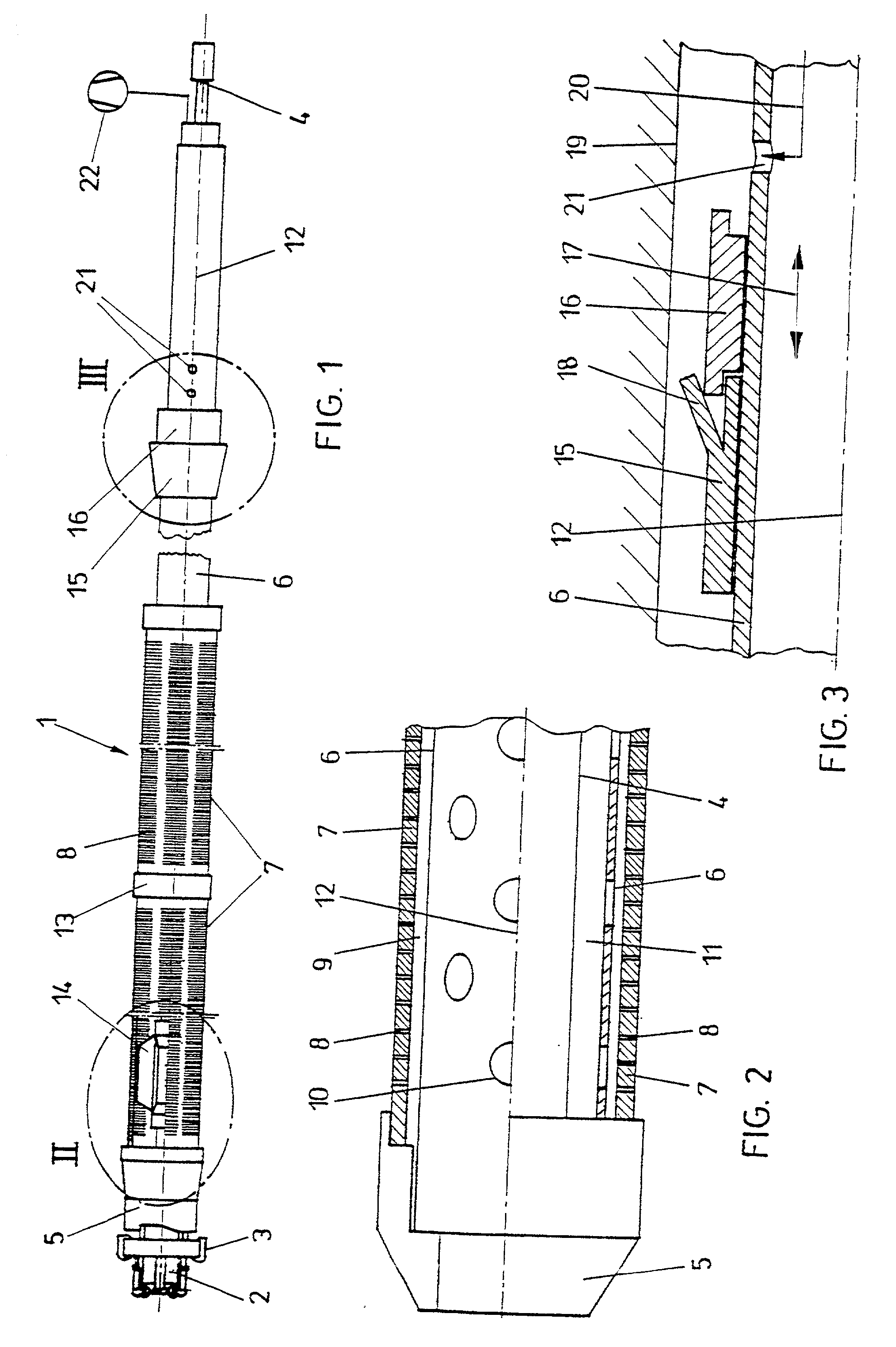
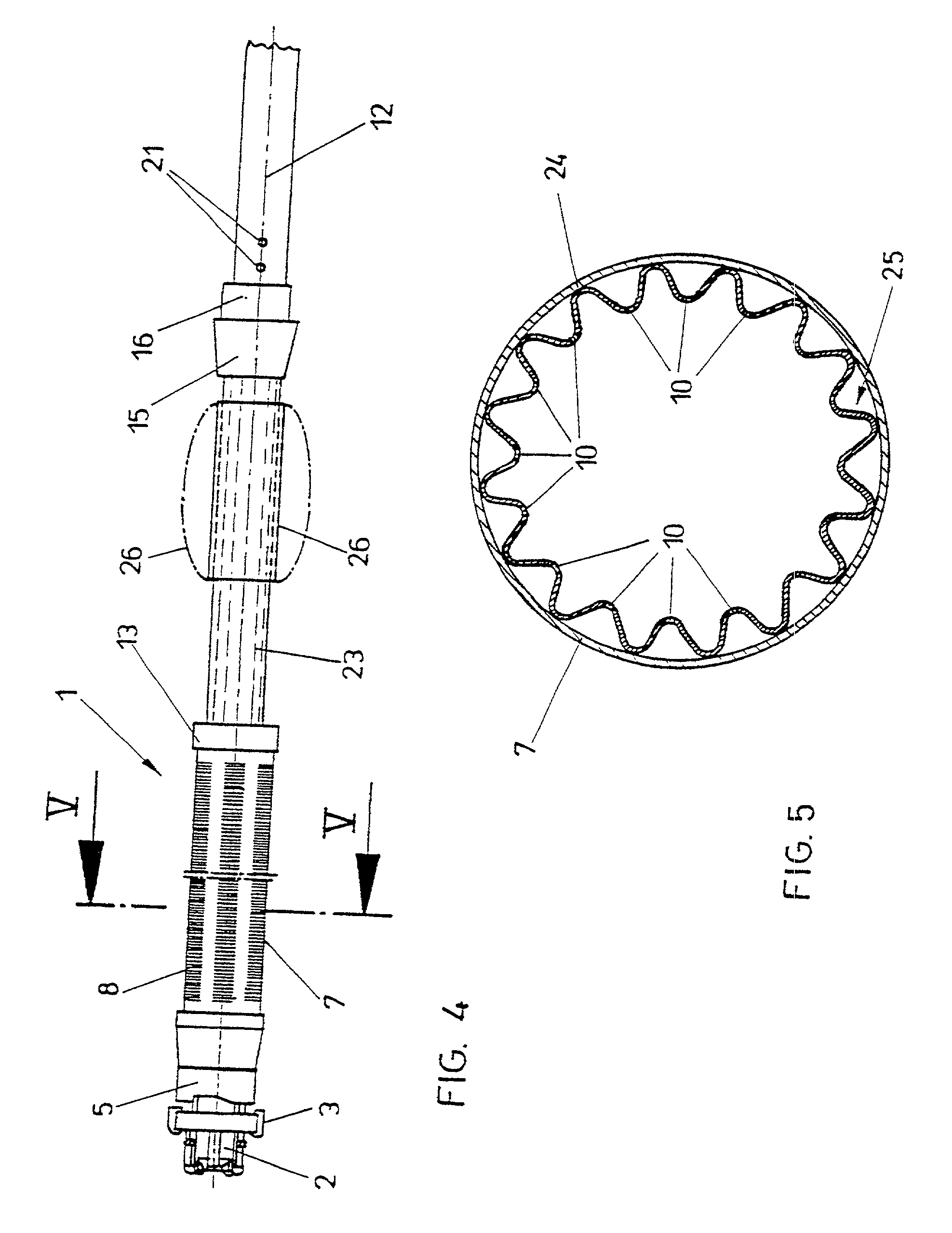
[0012] If the arrangement of one or several filtering tubes over a larger longitudinal extension of the jacket tube in the region following upon the drill bit is desired, it is, moreover, provided in a preferred manner that the annular space is defined by spacers arranged between the jacket tube and the filtering tube and / or by sleeve elements provided, in particular, in the end regions of the filtering tube such that the annular space required between the jacket tube and the filtering tube for a proper
filter effect even over larger lengths of a filtering section will be safely maintained.
[0014] In particular, when providing a filtering tube having a larger longitudinal extension or when providing several contiguous filtering tubes in order to be able to provide an accordingly long draining or
dewatering path, it is contemplated according to another preferred embodiment that the jacket tube in its section surrounded by the filtering tube is provided with a plurality of passage openings arranged distributedly about its circumference, particularly in a uniform manner, the clear width of which passage openings exceeds the clear width of the passage openings or slits formed in the filtering tube so as to enable an accordingly safe extraction of the fluid through the annular space provided between the jacket tube and the drill rod assembly. By
dimensioning the passage openings or slits on the circumference of the jacket tube accordingly larger, the possibility of an immediate transportation of the fluid will, moreover, be ensured even when providing a smaller amount of passage openings or slits. Obstruction of the passage openings or slits provided in the jacket tube need not be feared in that case, since the filtering tube is designed with accordingly smaller passage openings or slits so that the entry of larger particles need not be feared. Furthermore, it is also feasible by an appropriate distribution of the passage openings or slits in the jacket tube to devise the configuration in a manner that no excessive weakening of the
mechanical strength or resistance of the jacket tube need be feared.
[0017] In order to assist any desired drainage, it is suggested according to a further preferred embodiment that a sealing element is provided on the external circumference of the jacket tube at a distance from the filtering tube on the end facing away from the drill bit and that in the jacket tube, on the end facing away from the filtering tube, at least one outlet opening for delivering a filling
mass, in particular a hardening suspension, is provided in the vicinity of the sealing element. By means of such a sealing element, which enables the sealing of a drill hole relative to surrounding rock, in particular upon delivery of the filling
mass, in particular a hardening suspension such as, for instance, concrete or the like, not only the path or length of the drill hole provided for draining will be precisely defined, but such sealing also prevents fluid possibly present in the region of the drill bit from spreading within the drill hole along the external side of the jacket tube, thereby causing, for instance, the flushing, or undesired enlargement of the dimensions, of the drill hole as might be feared, for instance, at the occurrence of water with a roof bolt to be set in a roof, in which case the drill hole opening extends inclinedly downwards and fluid present in the rock could flow off outside the jacket tube.
[0018] In order to enable accordingly simple sealing, the configuration preferably is devised such that the sealing element is comprised of a lip-shaped or tongue-shaped synthetic element annularly surrounding the jacket tube and capable of being widened upon introduction of the filling
mass, wherein, in this respect, it is, furthermore, suggested in a preferred manner that the sealing element is formed with a
hardness of 80 to 100
Shore and, in particular, 90
Shore. While maintaining a suitable
mechanical strength or resistance of the sealing element, this also results in the respective elasticity allowing for proper widening, and hence abutting of the sealing element on the wall of the produced drill hole, upon introduction of a filling mass.

