Plasma display panel

a technology of display panel and plasma, which is applied in the direction of static indicating devices, gas discharge vessels/containers, instruments, etc., can solve the problems of reducing the brightness of the pdp, and reducing the luminance of the back phosphor layer over time, so as to maintain the color balance of the pdp for a long time, the effect of accelerating the luminance degradation speed

Inactive Publication Date: 2001-06-21
PANASONIC CORP
View PDF0 Cites 14 Cited by
  • Summary
  • Abstract
  • Description
  • Claims
  • Application Information

AI Technical Summary

Benefits of technology

[0016] The first object can be fulfilled by providing front phosphor layers respectively in opposition to back phosphor layers, other than a back phosphor layer whose luminance degrades fastest with time, among red, green, and blue back phosphor layers. Since the front phosphor layers are susceptible to luminance deterioration due to ultraviolet radiation and ion bombardment, they serve to accelerate the luminance degradation speeds of the opposite back phosphor layers. Accordingly, the luminance degradation speeds of the back phosphor layers combined with the front phosphor layers are brought to be more balanced with the luminance degradation speed of the back phosphor layer whose luminance degrades fastest, with it being possible to maintain the color balance of the PDP for a long time.
[0017] The second object can be fulfilled by providing front phosphor layers respectively in opposition to back phosphor layers, other than a back phosphor layer whose initial luminance utilization factor is the lowest among the red, green, and blue back phosphor layers. In so doing, the back phosphor layers combined with the front phosphor layers increase in luminance, so that the brightness of the PDP in its initial state can be improved while maintaining favorable color balance.
[0018] High brightness and favorable color balance of the PDP can also be attained by providing front phosphor layers respectively in opposition to the red, green, and blue back phosphor layers, and setting the visible light transmittance of each front phosphor layer in accordance with the initial luminance of its opposite back phosphor layer.
[0019] Here, by using spherical phosphor particles obtained by hydrothermal synthesis for such front and back phosphor layers, the brightness of the PDP is further enhanced.

Problems solved by technology

Nevertheless, the PDP has the following problems associated with color temperatures.
This means the luminance of each back phosphor layer degrades over time.
This disturbs the color balance of the PDP when displaying a white color, and results in a drop in color temperature.
However, such limited use of the luminance of the red and green phosphors causes a decrease in brightness of the PDP.

Method used


Image

  • Plasma display panel
  • Plasma display panel
  • Plasma display panel

Examples


first embodiment

[0033] First Embodiment

[0034] A PDP and a PDP-equipped display device of the first embodiment of the invention is described below, with reference to drawings.

[0035] (Construction of a PDP 100)

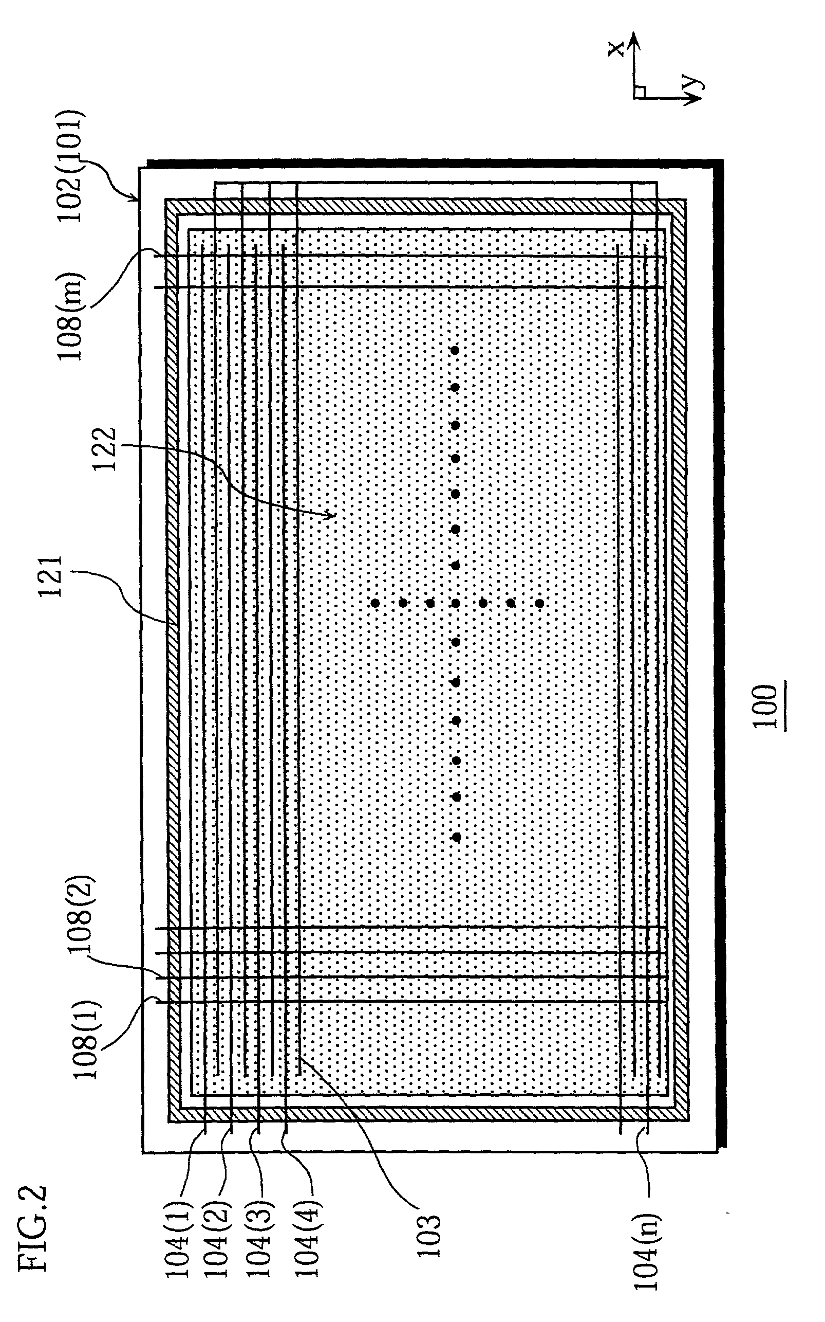
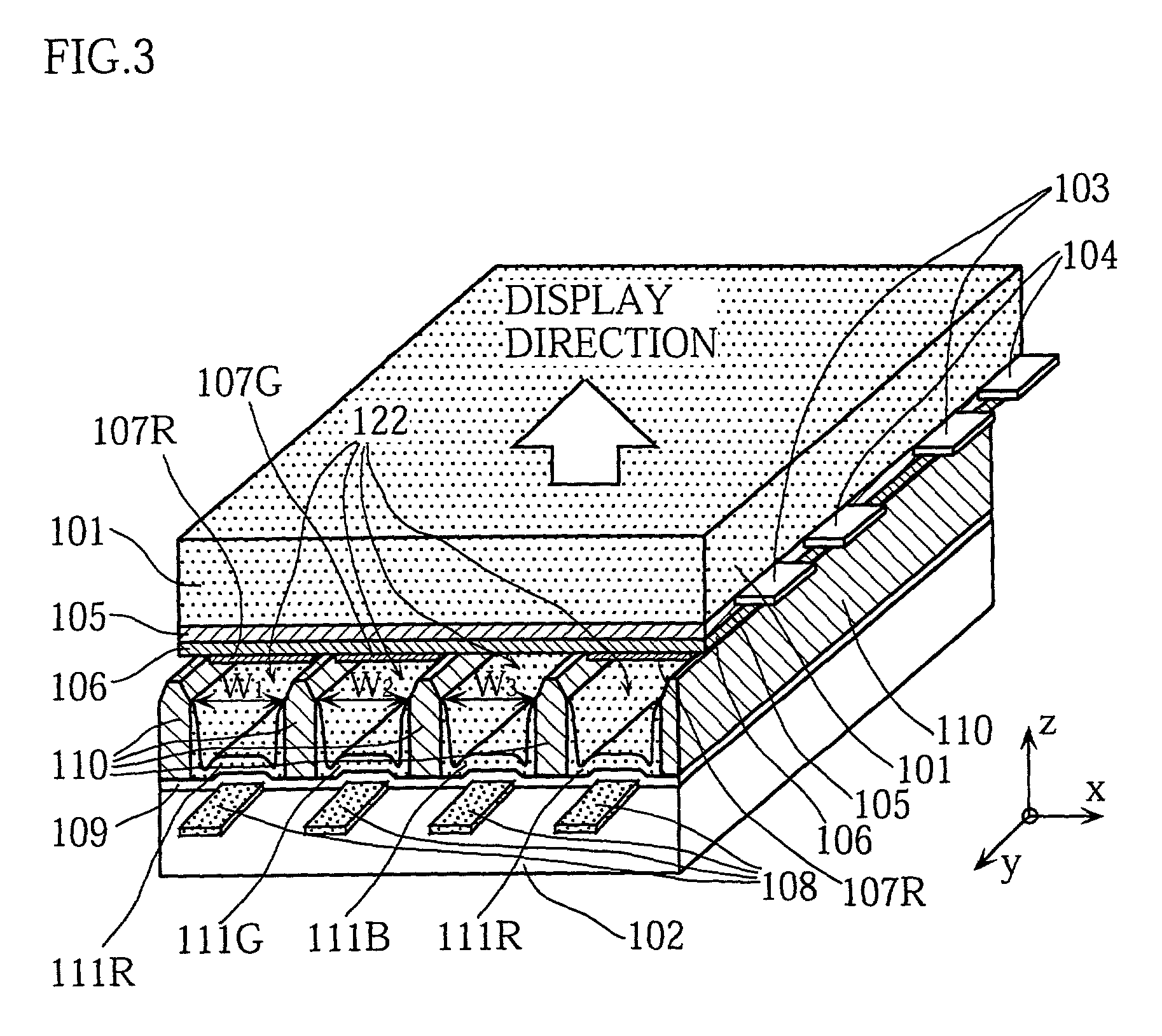
[0036] FIG. 2 is a schematic plan view of a PDP 100 from which a front glass substrate 101 has been removed, whereas FIG. 3 is a partial perspective and sectional view of the PDP 100. Note that in FIG. 2 some of display electrodes 103, display scan electrodes 104, and address electrodes 108 are omitted for simplicity's sake. A construction of this PDP 100 is explained with reference to these drawings.

[0037] In FIG. 2, the PDP 100 is roughly made up of a front glass substrate 101 (not illustrated), a back grass substrate 102, n display electrodes 103, n display scan electrodes 104, m address electrodes 108, and an airtight sealing layer 121 (the diagonally shaded area in the drawing). The n display electrodes 103, the n display scan electrodes 104, and the m address electrodes 108 together form ...

first experiment

[0129] (First Experiment)

[0130] (Samples Nos. 1 and 2)

[0131] In a sample No. 1, front phosphor layers are provided for red and green. In a sample No. 2, front phosphor layers are provided for red.

[0132] In both samples, the following phosphor particles are used.

2 Red phosphor: (Y,Gd)BO.sub.3:Eu Green phosphor: Zn.sub.2SiO.sub.4:Mn Blue phosphor: BaMgAl.sub.10O.sub.17:Eu

[0133] Also, both samples are 42-inch PDPs in which the height of the barrier ribs 110 is 0.1 mm, and the distance between neighboring barrier ribs 110, i.e. the cell pitch, is 0.36 mm. A discharge gas formed by a mixture of xenon (5%) and neon (95%) is filled in the discharge spaces 122 at a pressure of 66500 Pa. Also, in both back and front phosphor layers of the same color, phosphor particles created by the same manufacturing method are used.

[0134] (Sample No. 3)

[0135] In a sample No. 3 (reference sample), no front phosphor layers are provided. Apart from this difference, the sample No. 3 is the same as the samples...

second embodiment

[0144] Second Embodiment

[0145] The following is a description of a PDP according to the second embodiment of the invention, with reference to drawings.

[0146] The PDP of the second embodiment has a construction similar to the PDP of the first embodiment shown in FIGS. 2 to 5, and differs with the first embodiment only as to which of the three colors is provided with front phosphor layers. The following description focuses on this difference.

[0147] FIG. 10 is a partial perspective and sectional view of the PDP of the second embodiment. Note here that construction elements which are the same as those in the first embodiment shown in FIG. 3 have been given the same reference numerals and their explanation has been omitted.

[0148] In this PDP, a front phosphor layer 107B is provided in opposition to the back phosphor layer 111B whose initial luminance is the lowest of the back phosphor layers 111R, 111G, and 111B.

[0149] When the conventionally known red phosphor (Y,Gd)BO.sub.3:Eu, green p...


PUM


Abstract

A PDP that can maintain favorable color balance is provided. In the PDP which is equipped with back phosphor layers of the three colors red, green, and blue in a back panel, front phosphor layers are provided in a front panel respectively in opposition to back phosphor layers other than the back phosphor layer whose luminance degrades fastest with time among the red, green, and blue back phosphor layers. These front phosphor layers are prone to luminance deterioration caused by ultraviolet radiation or ion bombardment, and therefore accelerate the luminance degradation speeds of their opposite back phosphor layers. Accordingly, the luminance of light emitted from each of the two combinations of the front and back phosphor layers is brought to be more balanced with the luminance of light emitted from the back phosphor layer with the highest luminance degradation speed. Hence the PDP can maintain favorable color balance over a long time.

Description

[0001] 1. Field of the Invention[0002] The present invention relates to a plasma display panel for use in a display device or the like, and in particular relates to a plasma display panel that offers excellent color balance.[0003] 2. Related Art[0004] Among various types of color display devices used for displaying images on computers, televisions, and the like, a plasma display panel (hereinafter, "PDP") has become a focus of attention as a color display device that can realize a slim, lightweight, large-screen display device.[0005] FIG. 1 is a partial perspective and sectional view of a conventional, typical PDP.[0006] In this PDP, a front glass substrate 11 and a back glass substrate 12 are placed in opposition to each other, with barrier ribs 19 being interposed in between. On the surface of the front glass substrate 11 facing the back glass substrate 12, a plurality of display electrodes 13 and a plurality of display scan electrodes 14 (only two pairs of them are shown in the d...

Claims


Application Information

Patent Timeline
Patent Type & Authority Applications(United States)
IPC IPC(8): G09G3/28H01J11/12H01J11/42H01J17/16H01J17/49
CPCH01J11/12H01J11/42
Inventor KADO, HIROYUKIMIYASHITA, KANAKO
Owner PANASONIC CORP
Why Eureka
Try Eureka