
A Method Of Fabricating A DRAM Transistor With A Dual Gate Oxide Technique

a technology of dram transistor and oxide, which is applied in the direction of semiconductor devices, basic electric elements, electrical equipment, etc., can solve the problems of reducing rowline capacitance, reducing access speed, and more problematic problems

Inactive Publication Date: 2001-07-19
ROUND ROCK RES LLC
View PDF0 Cites 63 Cited by
  • Summary
  • Abstract
  • Description
  • Claims
  • Application Information

AI Technical Summary

Benefits of technology

This approach improves access speed, reduces static refresh times, enhances subthreshold voltage, and decreases gate-induced drain leakage, while simplifying the fabrication process by eliminating the need for separate masks and reducing steps.

Problems solved by technology

In other words, an increase in either the resistance of the capacitance of the rowline will degrade access speed.
The reduction of rowline capacitance, however, is more problematic.

Method used


Image

  • A Method Of Fabricating A DRAM Transistor With A Dual Gate Oxide Technique
  • A Method Of Fabricating A DRAM Transistor With A Dual Gate Oxide Technique
  • A Method Of Fabricating A DRAM Transistor With A Dual Gate Oxide Technique

Examples


Embodiment Construction

hereinbelow.

[0014] For the present invention to be clearly understood and readily practiced, the present invention will be described in conjunction with the following figures wherein:

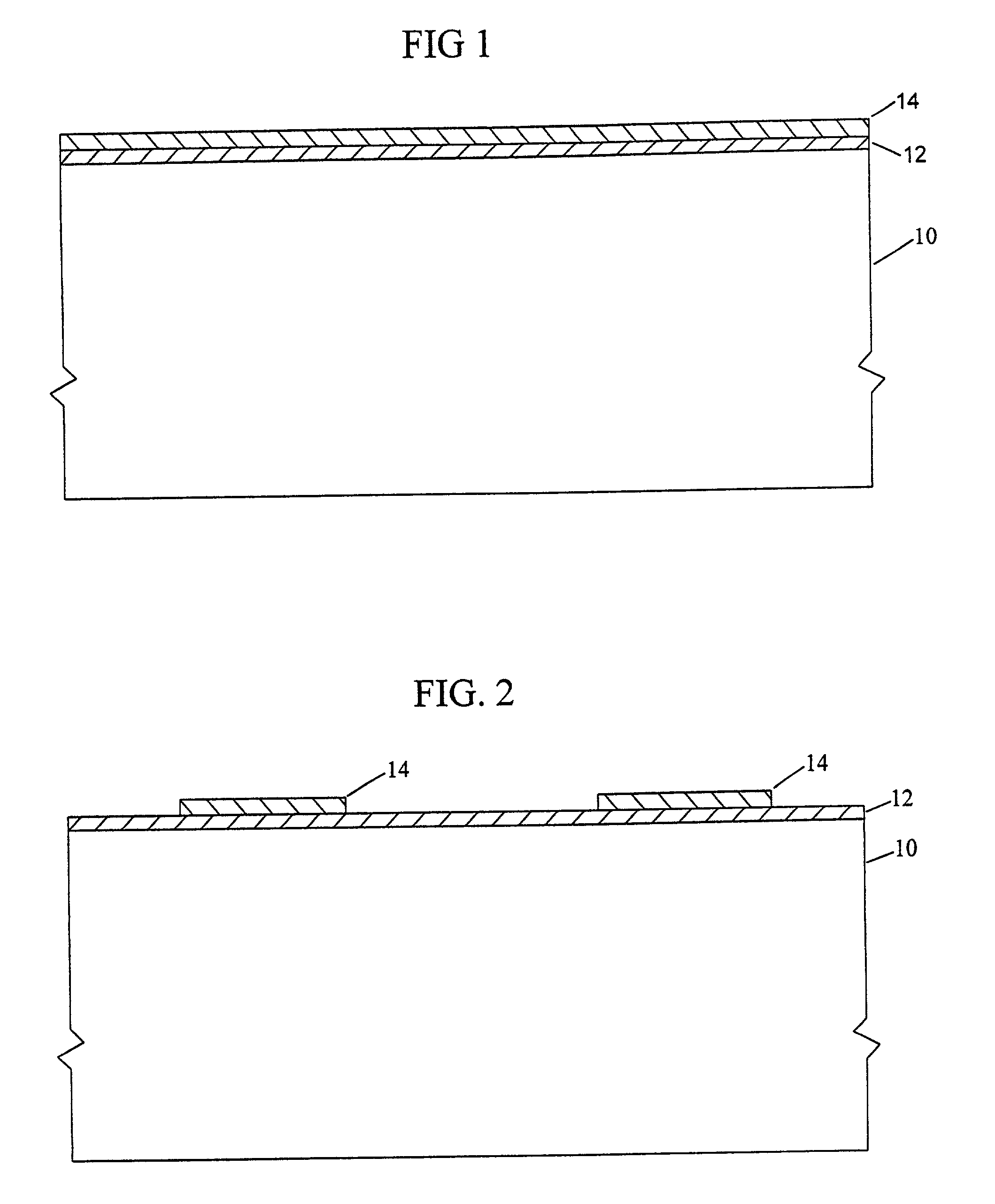
[0015] FIG. 1 illustrates a substrate with a first gate oxide layer grown on a surface thereof and a layer of silicon nitride deposited on top of the gate oxide layer;

[0016] FIG. 2 illustrates the substrate of FIG. 1 after the silicon nitride layer has been patterned with a photoresist mask to define oxide regions which will become future active areas;

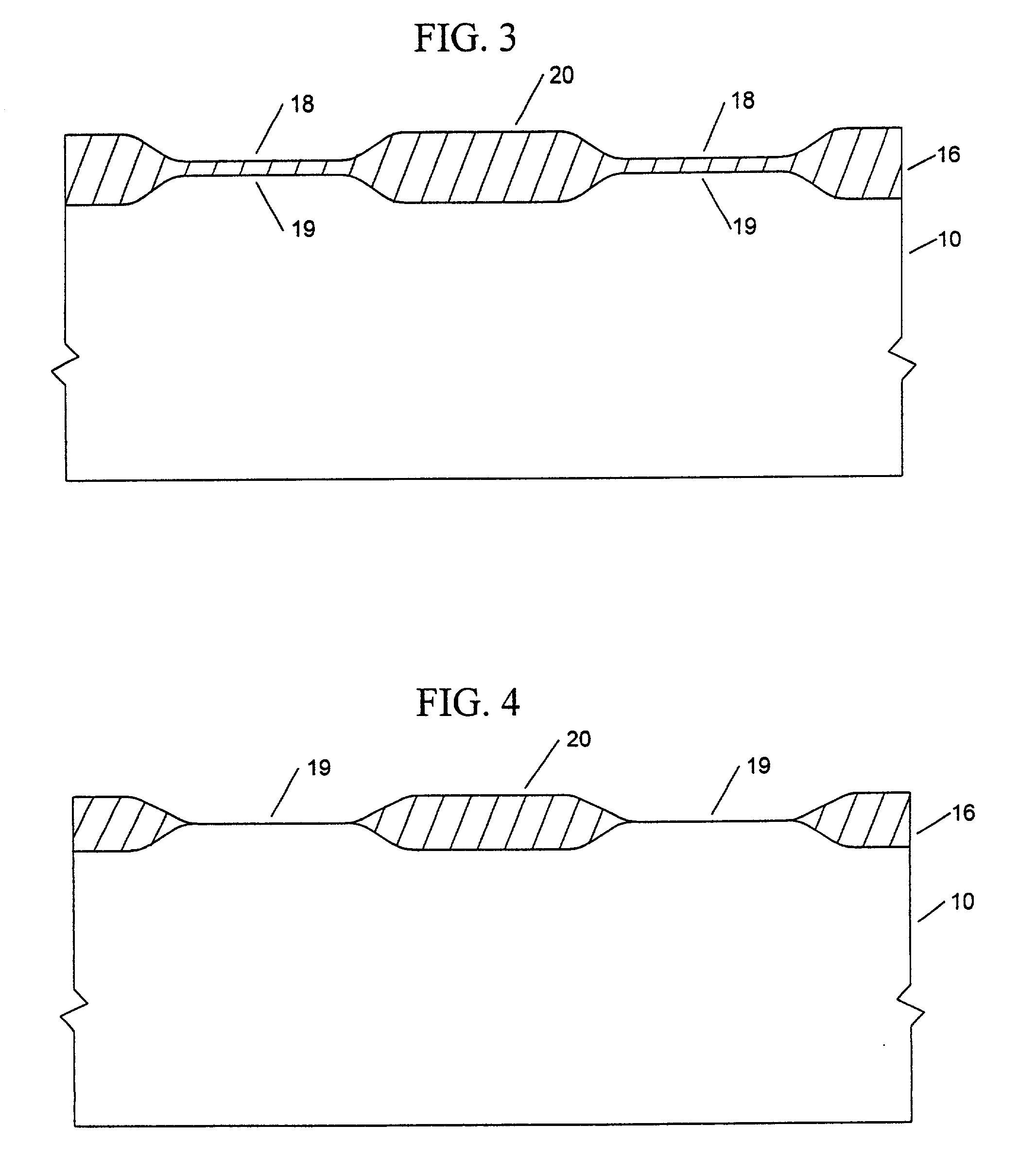
[0017] FIG. 3 illustrates the substrate of FIG. 2 after an oxide layer has been thermally grown on the upper surfaces of the substrate not covered by the remnants of the silicon nitride layer and after the remnants of the silicon nitride layer have been removed;

[0018] FIG. 4 illustrates the substrate of FIG. 3 after the pad oxide has been stripped to expose the substrate in the regions which will become future active areas;

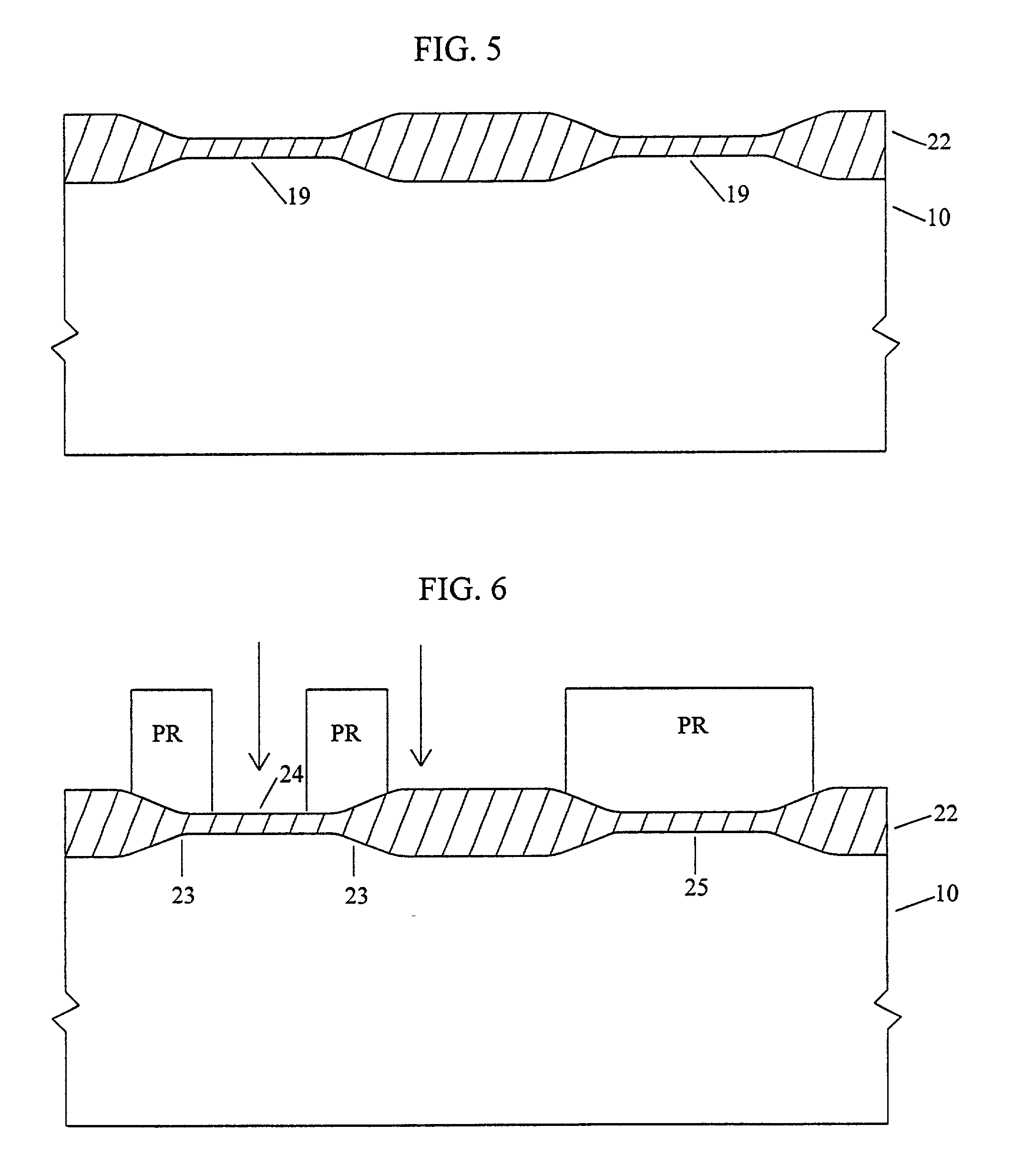
[0019] FIG. 5 illustrates the sub...


PUM

PropertyMeasurementUnit
thicknessaaaaaaaaaa
thickaaaaaaaaaa
thicknessaaaaaaaaaa

Abstract

The process comprises the steps of growing a first oxide layer on the upper surface of a substrate; depositing a silicon nitride layer on top of the first oxide layer; patterning the silicon nitride layer with a photoresist mask to define field oxide areas; stripping the oxide layer and regrowing a pad oxide layer on the upper surfaces of the substrate not covered by the remnants of the silicon nitride layer; removing the remnants of the silicon nitride layer; stripping the pad oxide layer and growing a sacrificial oxide layer; masking the sacrificial oxide layer with a photoresist to protect the area where the memory array will be formed; stripping the sacrificial oxide not protected by the photoresist; stripping the photoresist; and growing a gate oxide layer which is thinner than the sacrificial oxide layer. Thereafter, fabrication of the memory device may be completed using any known prior art techniques.

Description

[0001] 1. Field of the Invention[0002] The present invention relates to semiconductor fabrication techniques, and more particularly to techniques for fabricating dynamic random access memories (DRAM).[0003] 2. Description of the Background[0004] A DRAM array is comprised of individual memory cells arranged in columns and rows on a lightly-doped silicon substrate. Each cell has a field-effect access transistor and a storage capacitor. The capacitor, which is directly connected to the transistor's source or storage node, may be charged and discharged through the transistor's channel. Transistor gates and gate interconnects within an array row are formed from a ribbon of conductive material which runs the length of the row. That conductive ribbon is known as a rowline. Between consecutive transistor gate within a row, the rowline traverses a field oxide region. In active areas of the array (locations where the rowline functions as a gate), the rowline is insulated from the substrate by...

Claims


Application Information

Patent Timeline
Patent Type & Authority Applications(United States)
IPC IPC(8): H01L21/469H10B12/00
CPCH01L27/10844H01L27/10852H01L27/10873H01L27/10894Y10S438/981Y10S148/116H10B12/01H10B12/033H10B12/05H10B12/09
Inventor GONZALEZ, FERNANDO
Owner ROUND ROCK RES LLC
Learn More